Heating device using industry kiln stove waste heat
A heating device and kiln technology, which can be applied to household heating, process efficiency improvement, furnaces and other directions, can solve problems such as increasing production costs, uneconomical, and polluting the environment, and save energy, reduce pollution, and save costs. Effect
- Summary
- Abstract
- Description
- Claims
- Application Information
AI Technical Summary
Problems solved by technology
Method used
Image

Examples
Embodiment Construction
[0009] The present invention will be further described below in conjunction with the accompanying drawings and specific embodiments.
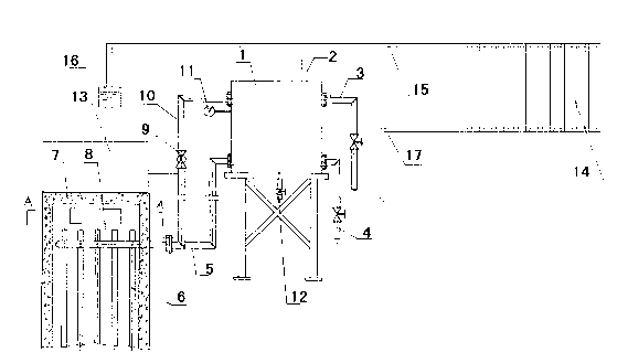
[0010] Referring to the accompanying drawings, the serpentine coil 8 is installed at the entrance of the flue in the furnace body 7 of the kiln, and several kiln hot air pipes 6 perpendicular to the coil 8 are arranged between the pipelines of the coil 8; The two ends of 8 pass through the furnace body 7, wherein one end communicates with the lower circulation pipe 5 installed below the thermal insulation water tank 1 through a flange, and the other end communicates with the upper circulation pipe 1 installed above the thermal insulation water tank 1 through another flange 0 is connected. The thermal insulation water tank 1 is installed on a position higher than the body of heater 7 by a support, and an outlet pipe 3 and a water replenishment pipe 4 are installed on the top of the thermal insulation water tank 1 other side. In order to ensure ...
PUM
 Abstract
Description
Claims
Application Information