Supercharge Your Innovation With Domain-Expert AI Agents!

A rotating anode CT tube

A technology of rotating anodes and bulbs, applied in discharge tubes, X-ray tubes, X-ray tube electrodes, etc., can solve the problems of poor heat dissipation effect and slow heat dissipation speed, and achieve high heat dissipation efficiency, increase speed and prolong service life. Effect

Active Publication Date: 2015-12-02
MING WEI MEDICAL TECH SUZHOU
View PDF5 Cites 0 Cited by
  • Summary
  • Abstract
  • Description
  • Claims
  • Application Information

AI Technical Summary

Problems solved by technology

However, the anode target of the traditional rotating anode CT tube is not in contact with the shell of the CT tube, so that the heat dissipation of the anode target can only be through thermal radiation and heat convection, and the heat dissipation speed is slow and the heat dissipation effect is poor.

Method used


Image

  • A rotating anode CT tube

Examples


Embodiment Construction

[0016] The present invention will be further described in detail below in conjunction with the accompanying drawings, so that those skilled in the art can implement it with reference to the description.

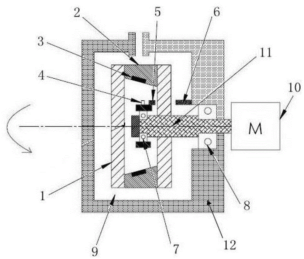
[0017] Such as figure 1 As shown, the present invention discloses a rotating anode CT tube, comprising: a tube core, which is a vacuum sealing device, including a metal tube shell, an anode target 3 connected to the tube shell, and an anode target 3 located in the tube shell. The cathode 4 in the bulb housing and corresponding to the position of the anode target 3; the bulb support 12, on which a cooling oil inlet and a cooling oil outlet are arranged, and the bulb core is accommodated in the bulb support In the inner cavity of the seat 12; the driving device, which drives the bulb housing and the anode target 3 connected to the bulb housing to rotate; the cathode static device, including the first magnet connected to the cathode 4 5 and the second magnet 6 corresponding to ...


PUM


Abstract

The invention discloses a rotating anode CT (computed tomography) bulb tube which comprises a bulb tube core, a bulb tube support (12), a driving device and a cathode static device. The bulb tube core is a vacuum sealing device and comprises a metal bulb tube shell, an anode target (3) and a cathode (4), the anode target (3) is connected into the bulb tube shell, the cathode (4) is positioned in the bulb tube shell and corresponds to the anode target (3), a cooling oil inlet and a cooling oil outlet are arranged on the bulb tube support (12), the bulb tube core is placed in an internal cavity of the bulb tube support (12), the driving device drives the bulb tube shell and the anode target (3) connected on the bulb tube shell to rotate, the cathode static device comprises a first magnet (5) and a second magnet (6), the first magnet (5) is connected on the cathode (4), and the second magnet (6) corresponds to the first magnet (5) and is connected on the bulb tube support (12). The CT bulb tube is fine in anode cooling effect, long in service life and high in rotating speed.

Description

technical field [0001] The invention relates to a CT bulb, in particular to a rotating anode CT bulb. Background technique [0002] CT machine is a full-featured disease detection instrument. With the development of technology, CT machine has been popularized due to its high resolution capability and intuitive and accurate diagnosis effect, and has been widely used in the medical field. CT tube, also known as X-ray tube, is the core component of CT machine and is used to generate X-rays. Whether the technology of CT tube is perfect or not directly affects the working effect of CT machine. [0003] A CT tube usually includes the following parts: shell, cathode, anode and so on. By pressurizing the cathode, the cathode emits electrons, which are focused to bombard the anode target. The anode target is bombarded by electrons to generate X-rays, and heat is generated and emitted. The power of traditional fixed anode CT bulbs is limited due to the high temperature of the anode...

Claims


Application Information

Patent Timeline
Patent Type & Authority Patents(China)
IPC IPC(8): H01J35/10H01J35/26
Inventor 周锐刘翔范韶锋
Owner MING WEI MEDICAL TECH SUZHOU
Features
  • R&D
  • Intellectual Property
  • Life Sciences
  • Materials
  • Tech Scout
  • Unparalleled Data Quality
  • Higher Quality Content
  • 60% Fewer Hallucinations
Learn More