Wind driven generator cable clamp

A technology of wind power generators and cable clamps, applied in the direction of electrical components, etc., can solve the problems of easy loosening of cable fastening and limited anti-loosening effect, and achieve the effects of prolonging the maintenance cycle, strong resistance to transmission, and not easy to loosen

Active Publication Date: 2015-07-08
JIANGSU GOLDWIND SCI & TECH CO LTD
View PDF6 Cites 0 Cited by
  • Summary
  • Abstract
  • Description
  • Claims
  • Application Information

AI Technical Summary

Problems solved by technology

[0005] However, for wind turbines, the frequent swaying and vibration of the nacelle and the tower will inevitably lead to frequent swaying and vibration of the cables. loose

Method used


Image

  • Wind driven generator cable clamp
  • Wind driven generator cable clamp
  • Wind driven generator cable clamp

Examples


Embodiment Construction

[0043] Hereinafter, embodiments of the present invention will be described in detail with reference to the accompanying drawings.

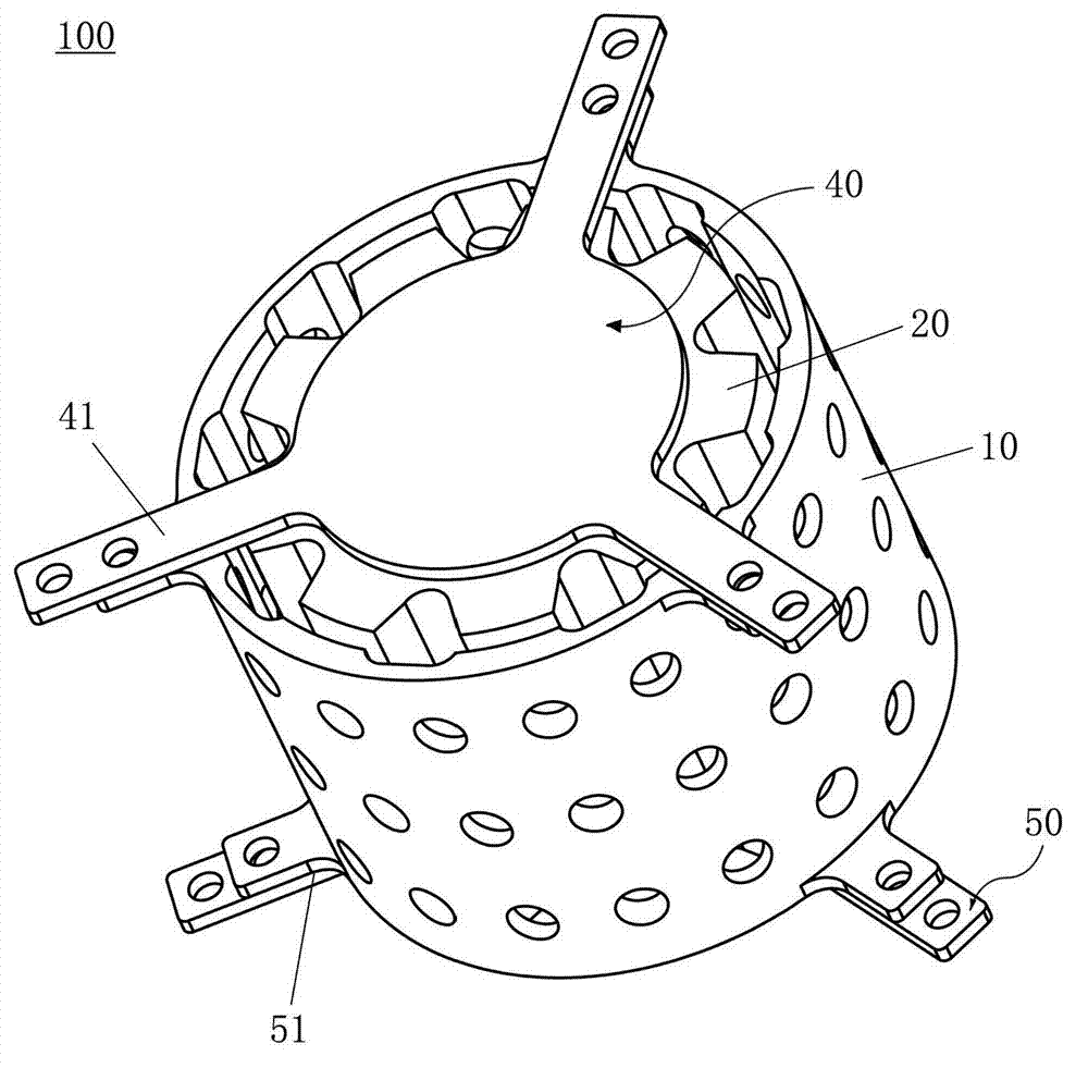
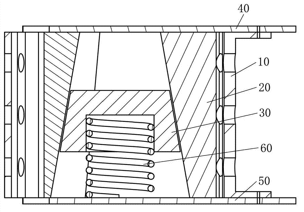
[0044] figure 1 is a perspective view showing a wind turbine cable clamp 100 according to an embodiment of the present invention; figure 2 is a sectional view showing the wind power generator cable clamp 100 according to the embodiment of the present invention.

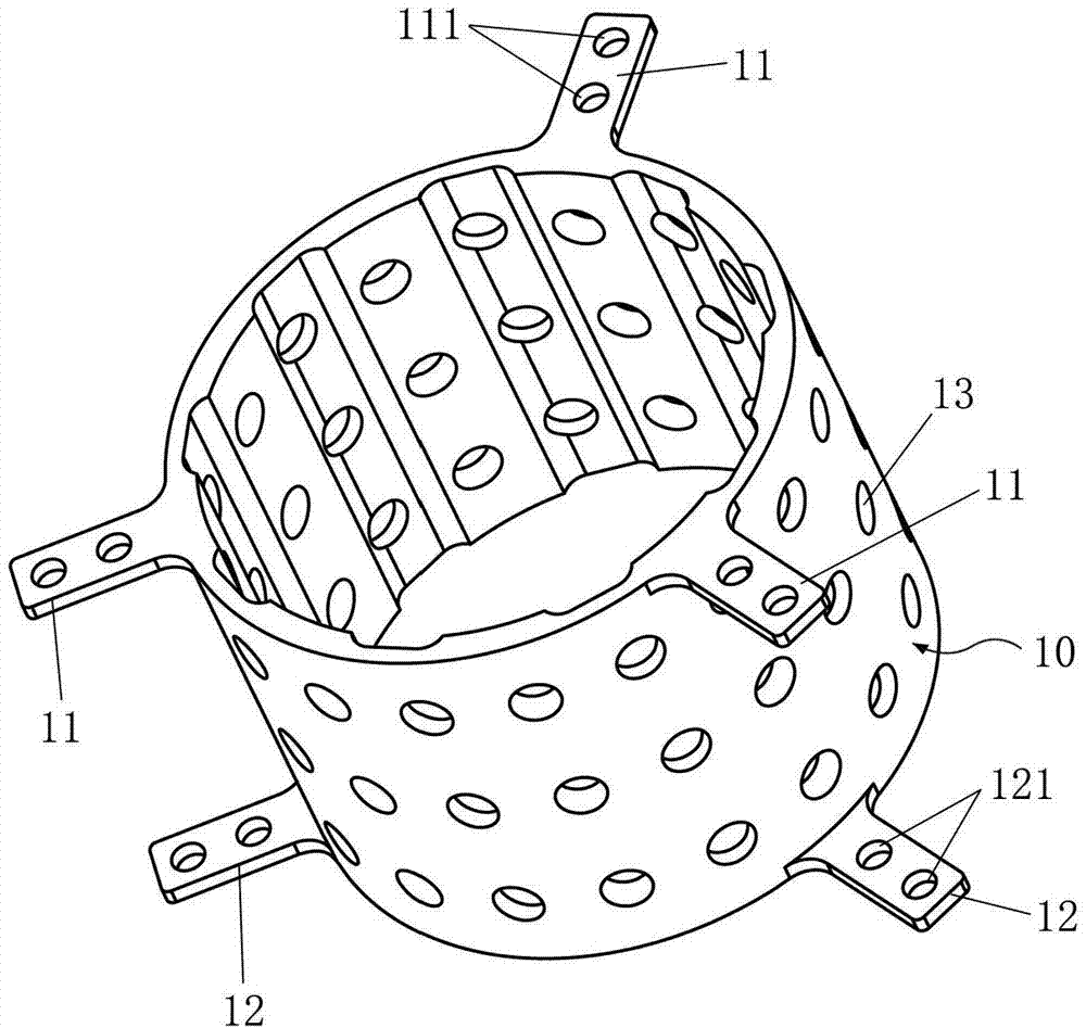
[0045] Such as figure 1 with figure 2 As shown, the wind power generator cable clamp 100 according to an embodiment of the present invention includes: an outer ring body 10; an inner ring body 20, which is arranged inside the outer ring body 10 and forms a Accommodates cable 70 (see Figure 7 ) space; the inner cone 30 is arranged in the inner ring body 20, and tends to automatically squeeze the inner ring body 20 outward; the lower cover plate 50 is arranged at the bottom of the cable clamp 100 and is fixed with the outer ring body 10 The ground connection is used to support the i...


PUM


Abstract

The invention provides a wind driven generator cable clamp. The cable clamp comprises an outer ring body and an inner ring body which is arranged in the outer ring body and formed by being surrounded by two blocky constructional elements, wherein a taper hole is formed by at least a portion of the inner peripheral surface of the inner ring body, which starts from one end of the inner ring body, and the inner diameters of the taper hole decrease from one end of the inner ring body towards the other end of the inner ring body. The cable clamp further comprises an inner cone which is arranged in the inner ring body and provided with a side surface of which the incline extent is consistent with the incline extent of the inner peripheral surface of the taper hole, and a lower cover plate which is arranged at the bottom of the cable clamp, connected with the outer ring body and used for supporting the inner ring body, wherein a certain interval is arranged between the inner ring body and the outer ring body under the state that a cable is clamped between the inner ring body and the outer ring body, and the inner cone automatically slide tending towards the other end of the inner ring body so as to push the inner ring body outward, and therefore the interval is adjusted. The cable clamp is reliable in performance, and the cable which is fastened is difficultly to loosen.

Description

technical field [0001] The present invention relates to a cable clamp, and more specifically relates to a wind power generator cable clamp installed in a tower of a wind power generator. Background technique [0002] A large number of cables are arranged inside the wind turbine, and these cables need to be drawn out from the nacelle, pass through the tower, and finally connect to the electrical cabinet at the bottom of the tower. The number of cables is large and the length is long, and basically all cables need to be routed from the inside of the tower. [0003] However, the height of the tower is generally more than 70 meters. When the cables are routed inside the tower, the cables must be fixed on the wall of the tower with cable clamps. Generally, a cable clamp is set every 2 meters. This is because: when the wind turbine is working, due to the wind load, the nacelle and the tower often sway and vibrate, and the cables will also sway and vibrate accordingly; after the u...

Claims


Application Information

Patent Timeline
IPC IPC(8): H02G3/02
Inventor 张建海朱海飞杨勇靖峰
Owner JIANGSU GOLDWIND SCI & TECH CO LTD
Why Eureka
Try Eureka