Gas-liquid separation tank for cold hydrogenation process

A gas-liquid separation tank and process technology, which is applied in the direction of using liquid separation agent, separation method, and dispersed particle separation, can solve the problems of space occupation and large size, and achieve the effect of saving space, small equipment size, and good separation effect

Inactive Publication Date: 2013-06-26
XIAN AEROSPACE YUANZHENG FLUID CONTROL
View PDF5 Cites 6 Cited by
  • Summary
  • Abstract
  • Description
  • Claims
  • Application Information

AI Technical Summary

Problems solved by technology

[0003] In order to solve the technical problem that the existing gas-liquid separation tank has a large size and occupies a large space, the invention provides a gas-liquid separation tank for cold hydrogenation process

Method used


Image

  • Gas-liquid separation tank for cold hydrogenation process
  • Gas-liquid separation tank for cold hydrogenation process

Examples


Embodiment Construction

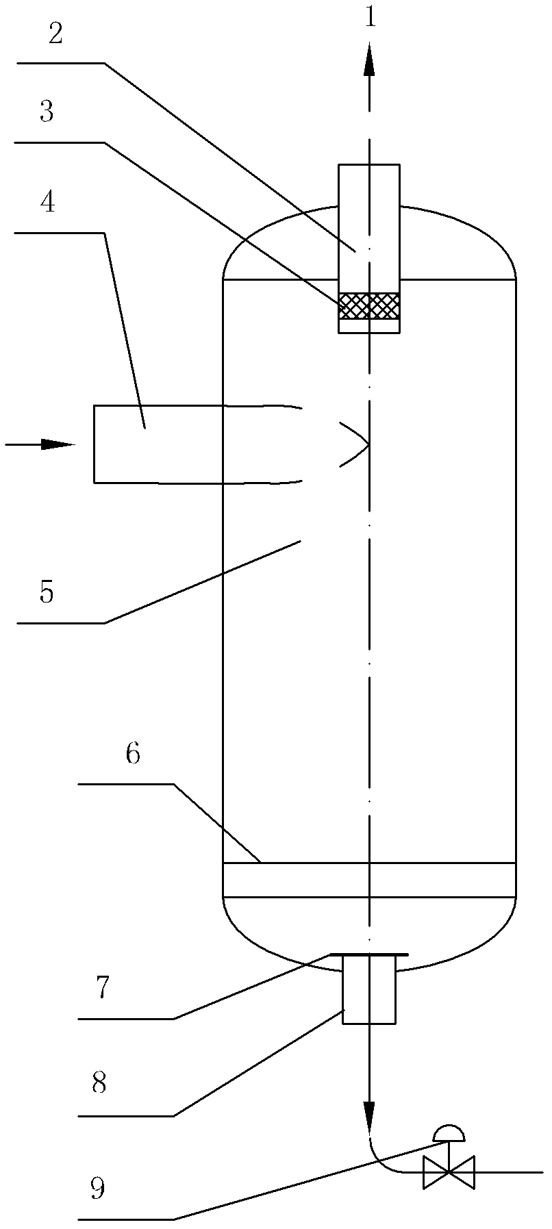
[0016] The invention is applied to the cold hydrogenation process of polysilicon, and is used for separating the gas-liquid two-phase medium discharged from the Venturi scrubber.

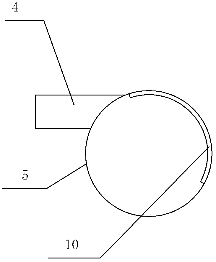
[0017] The structure of the separation tank is as follows: the equipment is an upright structure, the gas-liquid mixture is carried out by the tangential inlet, the gas phase outlet 1 is located at the top of the tank body 5, the liquid phase outlet 8 is located at the bottom of the tank body, and the gas phase outlet and the liquid phase outlet are on the same axis;

[0018] The inner surface of the equipment opposite to the tangential inlet has an anti-shock plate 10 attached to the inner surface of the equipment; the gas phase outlet has an overflow pipe 2 extending into the equipment tank for a certain length, and the overflow pipe is used to form a separation space to provide separation efficiency. It is also beneficial to replace the filter screen; the gas-liquid filter screen 3 is arranged in ...


PUM


Abstract

The invention relates to a gas-liquid separation tank for a cold hydrogenation process. The gas-liquid separation tank comprises a vertical tank body, a gas phase outlet, a liquid phase outlet, a liquid-level regulating valve and a two-phase outlet, wherein the gas phase outlet is formed above the tank body, the liquid phase outlet is formed below the tank body, the liquid-level regulating valve is arranged at the liquid phase outlet, and the two-phase outlet is formed in the middle of the tank body along the horizontal direction and is tangent with the inner wall of the tank body. According to the gas-liquid separation tank for the cold hydrogenation process, the technical problems that the conventional gas-liquid separation tank is relatively large in size and huge in occupied space are solved; and by adopting the vertical gas-liquid separation tank, the separation between reaction gas washed by utilizing a Venturi scrubber and scrubbing solution in the cold hydrogenation process can be realized, and the size of the device is minimized, so that the space is saved, and the cost is lowered.

Description

technical field [0001] The invention relates to a gas-liquid separation tank, which is applied to the cold hydrogenation process of polysilicon. Background technique [0002] At present, the mainstream polycrystalline hydrogenation process is divided into thermal hydrogenation process and cold hydrogenation process. The cold hydrogenation process has a wider development space because of its lower energy consumption than the thermal hydrogenation process. However, the gas-liquid separation tank of the existing cold hydrogenation process is relatively large in size and takes up a lot of space. Contents of the invention [0003] In order to solve the technical problem that the existing gas-liquid separation tank has a large size and occupies a large space, the invention provides a gas-liquid separation tank for cold hydrogenation process. [0004] Technical solution of the present invention: [0005] A gas-liquid separation tank for a cold hydrogenation process, which is sp...

Claims


Application Information

Patent Timeline
Patent Type & Authority Applications(China)
IPC IPC(8): B01D47/10
Inventor 邓肇冬
Owner XIAN AEROSPACE YUANZHENG FLUID CONTROL
Why Eureka
Try Eureka