A method for preparing δ-type cemented carbide micro milling cutter

A technology of cemented carbide and micro milling cutters, which is applied in the manufacture of tools, metal processing equipment, electrochemical processing equipment, etc., can solve the problems of low processing efficiency, material overcut, and the limitation of the minimum diameter of the tool, so as to improve processing efficiency, The effect of accelerating discharge

Inactive Publication Date: 2015-10-07
SHANDONG UNIV OF TECH
View PDF7 Cites 0 Cited by
  • Summary
  • Abstract
  • Description
  • Claims
  • Application Information

AI Technical Summary

Problems solved by technology

After wire electric discharge grinding (WEDG) processing, electric erosion pits will be formed on the cutting edge and cutting surface of the tool, and thus surface deterioration layers, microscopic cracks and residual tensile stress will be formed; laser processing also has defects similar to WEDG, laser processing The conduction of heat in the micro milling cutter will form a heat-affected zone, and microscopic cracks and thermal stress also exist in this area; precision micro-grinding can meet the process requirements of micro-milling cutter preparation to a certain extent, but affected by the grinding force, its The minimum diameter of the tool that can be stably obtained is limited; when the focused ion beam sputtering (FIB) process is used to prepare micro milling cutters, while ensuring high precision, there are also disadvantages such as low processing efficiency and high cost, and it is impossible to realize large-scale preparation of micro milling cutters. Milling cutter; Electrolytic EDM has the defect that material overcutting is serious and machining accuracy is difficult to guarantee

Method used


Image

  • A method for preparing δ-type cemented carbide micro milling cutter
  • A method for preparing δ-type cemented carbide micro milling cutter
  • A method for preparing δ-type cemented carbide micro milling cutter

Examples


Embodiment Construction

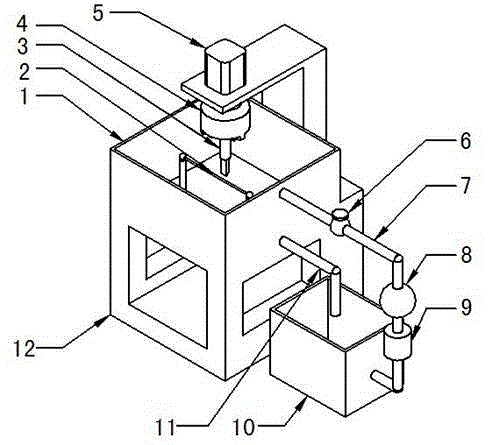
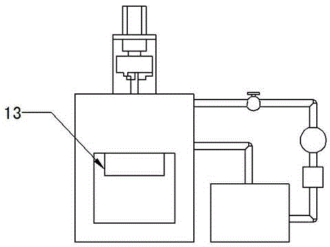
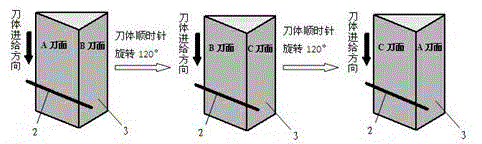
[0024] Such as figure 1 and 2 The device for preparing Δ-type cemented carbide micro-milling cutters combined with ultrasonic-assisted micro-electrolysis includes: electrolyte tank 1, which provides a processing environment for micro-electrolysis; tool electrode wire 2, which is fixed by a positioning fixture, and used for preparation after power-on Δ-type cemented carbide micro milling cutter 3; tool holder 4, used to move and clamp Δ-type carbide micro-milling cutter, and make the milling cutter reach the processing position through control; motor 5, provide power for the rotation of the tool holder; valve 6 , to control the circulation of the electrolyte between the electrolyte storage tank and the electrolyte tank, and stop the flow when it is closed; the electrolyte tank inlet pipe 7 makes the electrolyte flow into the electrolyte tank; the pressure pump 8 provides power to make the electrolysis The liquid flows into the electrolyte tank from the electrolyte storage tank...


PUM

PropertyMeasurementUnit
diameteraaaaaaaaaa

Abstract

The invention provides a method for manufacturing a delta type hard alloy micro milling cutter by the combination of ultrasonic auxiliary micro electrolysis. The method comprises the following steps: placing the delta type hard alloy micro milling cutter into a cutter clamp to be fixedly and firmly clamped; inputting machining data according to a size and requirements of a cutter to be machined, and getting ready for machining; opening a valve before the machining to enable electrolyte to enter an electrolyte tank through a filter and an electrolyte tank liquid inlet tube under the function of a force pump; starting an ultrasonic auxiliary device and a motor when a liquid level reaches a certain height; and machining the cutter with a tool (an electric wire) while the electrolyte is disturbed with ultrasonic, wherein the electrolyte flows back to an electrolyte storage box through an electrolyte tank liquid discharge tube at the same time, and the electrolyte is enabled to flow circularly between the electrolyte tank and the electrolyte storage box. Ultrasonic acceleration micro electrolytic machining is utilized for achieving the forming of a hard alloy micro milling cutter cutting edge and a hard alloy micro milling cutter cutting faces, and the delta type hard alloy micro milling cutter can be manufactured with high precision, high efficiency and low cost.

Description

technical field [0001] The invention belongs to the technical field of milling cutter preparation, in particular to a method for preparing a Δ-type cemented carbide micro milling cutter. Background technique [0002] At present, researchers from various countries have made some research progress in the preparation of micro-milling cutters and the application of micro-milling processes, but there are still many serious problems in the design, preparation and use of micro-milling cutters. There are insurmountable flaws. At present, the process methods for preparing micro milling cutters are: (1) wire electric discharge grinding process (WEDG); (2) laser machining process; (3) precision micro grinding process; (4) focused ion beam sputtering process ( FIB); (5) Electrolytic EDM composite micromachining device. After wire electric discharge grinding (WEDG) processing, electric erosion pits will be formed on the cutting edge and cutting surface of the tool, and thus surface det...

Claims


Application Information

Patent Timeline
Patent Type & Authority Patents(China)
IPC IPC(8): B23H3/00B23H7/38
Inventor 季画孙建军李志永
Owner SHANDONG UNIV OF TECH
Why Eureka
Try Eureka