Sleeve installed on medium carriage

A technology of sleeves and carriages, applied in positioning devices, clamping, supporting, etc., can solve the problems of high labor intensity and time delay, and achieve the effect of simple manufacturing method, low cost and high economic benefit

Inactive Publication Date: 2013-06-26
孙效
View PDF8 Cites 0 Cited by
  • Summary
  • Abstract
  • Description
  • Claims
  • Application Information

AI Technical Summary

Problems solved by technology

In actual operation, every time a tool is used, the tailstock must be manually moved back and forth, and the handwheel must be manually turned, which is time-consuming and labor-intensive.

Method used


Image

  • Sleeve installed on medium carriage

Examples


Embodiment Construction

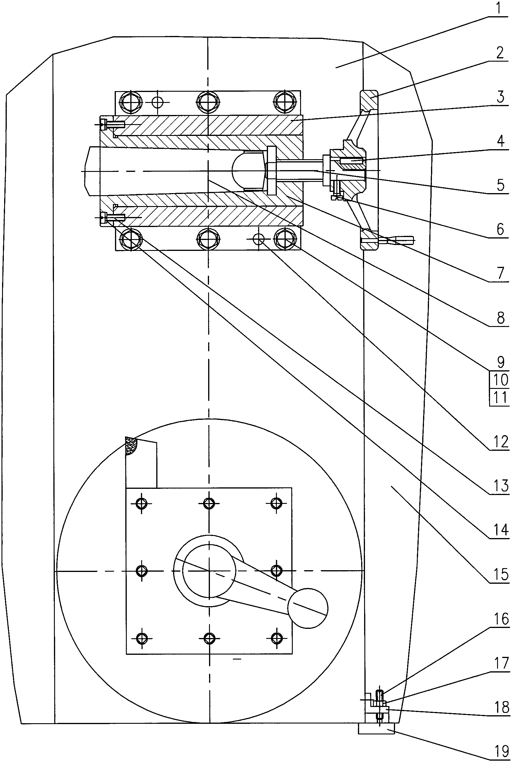
[0011] The quick tool unloader of the lathe is installed on the middle carriage (1) of the lathe and moves together with the large sliding plate (15) of the lathe to realize automatic tool feeding. In the accompanying drawings, the seat (3) is fixed on the carriage (1) in the lathe with a flat washer (10), a large spring washer (11), an internally threaded tapered pin (12) and a bolt (9), and the knife barrel (7 ) is fixed in the inner hole of the seat (3) with a slotted cylindrical head screw (13) and a small spring washer (14), the fit is H7 / h6, and the heat treatment of the knife cylinder (7) is 48~52HRC. The axis of the tapered hole of the tool barrel (7) where the tool (8) is installed is coaxial with the axis of rotation of the lathe spindle, and the hand wheel (2) is fixed on the wire with a common flat key (4) and a slotted cylindrical head shaft screw (6). On the cylinder on the left side of the bar (5), the stud on the right side of the lead screw (5) is installed in...


PUM


Abstract

The invention discloses a sleeve installed on a medium carriage. According to the sleeve installed on the medium carriage, a base is fixed on the medium carriage of a lathe, a cutter barrel is fixed in an inner hole in the base, the axis of a taper hole of the cutter barrel is coaxial with the rotation axis of a lathe main shaft, a hand wheel is fixed on a cylinder on the left side of a lead screw, the right side of the lead screw is arranged in a screw hole of the cutter barrel, a fixing plate is fixed on a large slide carriage of the lathe, a support frame is fixed on the medium carriage of the lathe, a groove long cylindrical end set screw is arranged in a screw hole of the support frame and is locked by a nut, and the cylindrical end of the groove long cylindrical end set screw abuts against the fixing plate. A groove cylindrical head screw and a spring washer used by the cutter barrel are fixed in the inner hole of the base in a mode that the matching is H7 / h6 and hot processing of the cutter barrel is 48-52 HRC. Cutters required by machining can be fast replaced and installed in the cutter barrel on the medium carriage of the lather, machining of a hole can be achieved with a corresponding cutter by means of the function of mechanical cutter feeding function of the lathe, machining is fast, and labor is saved. A lathe fast cutter dismantling device is low in manufacturing cost and high in economic benefit.

Description

technical field [0001] The invention relates to an accessory of a metal processing machine tool, especially a sleeve mounted on a middle carriage. Background technique [0002] Workers in the mechanical industry know that drills, reamers and reamers are used to drill, ream or ream parts on a lathe, and these tools are installed in the tapered hole of the tailstock sleeve of the lathe. The process needs to be replaced. During actual operation, every time a tool is used, the tailstock must be manually moved back and forth once, and the handwheel is manually turned, which is time-consuming and labor-intensive. Contents of the invention [0003] The purpose of the present invention is to provide a sleeve mounted on the middle carriage, which can directly replace the cutting tools required for installation and processing in the cutter cylinder mounted on the middle carriage of the lathe when drilling, reaming and reaming. [0004] The purpose of the present invention is achie...

Claims


Application Information

Patent Timeline
Patent Type & Authority Applications(China)
IPC IPC(8): B23Q3/00B23B21/00
Inventor 孙效
Owner 孙效
Why Eureka
Try Eureka