Bottom die single-side locking mechanism

A locking mechanism and bottom mold technology, which can be applied to other household appliances, household appliances, applications, etc., can solve the problem of large volume of the bottom mold locking device, and achieve the effect of reducing the size of the equipment

Active Publication Date: 2013-06-26
JIANGSU NEWAMSTAR PACKAGING MACHINERY
View PDF5 Cites 0 Cited by
  • Summary
  • Abstract
  • Description
  • Claims
  • Application Information

AI Technical Summary

Problems solved by technology

It can be seen that the bottom mold locking device in this patent is bulky

Method used


Image

  • Bottom die single-side locking mechanism
  • Bottom die single-side locking mechanism

Examples


Embodiment Construction

[0016] The present invention will be further elaborated below in conjunction with the accompanying drawings.

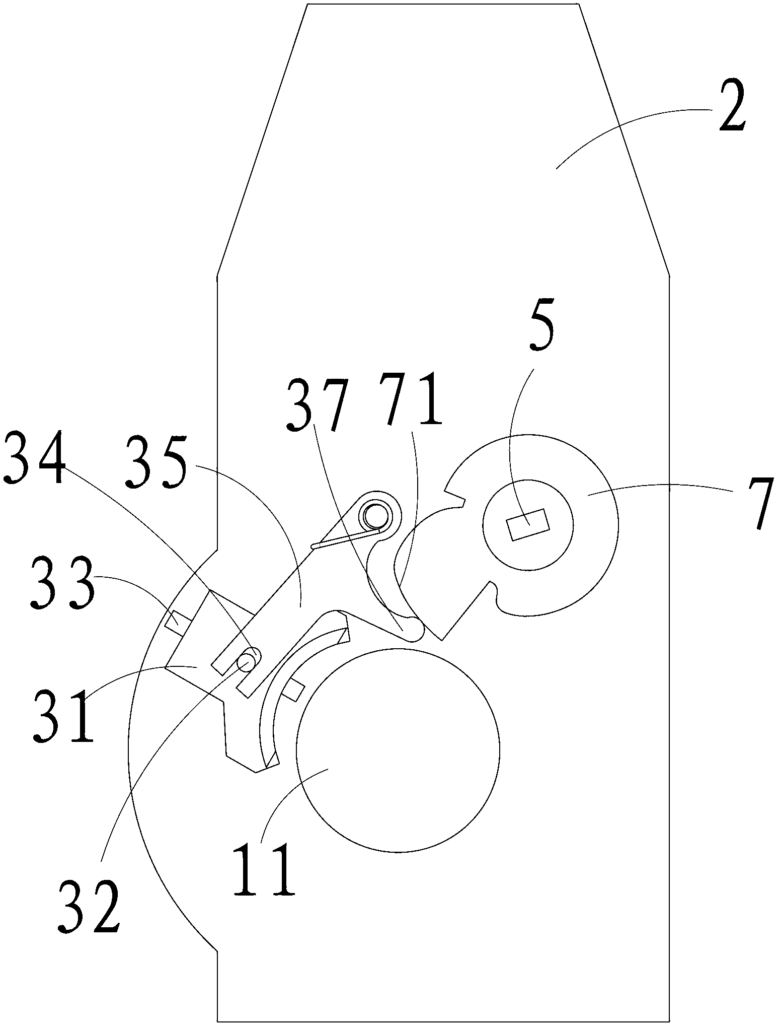
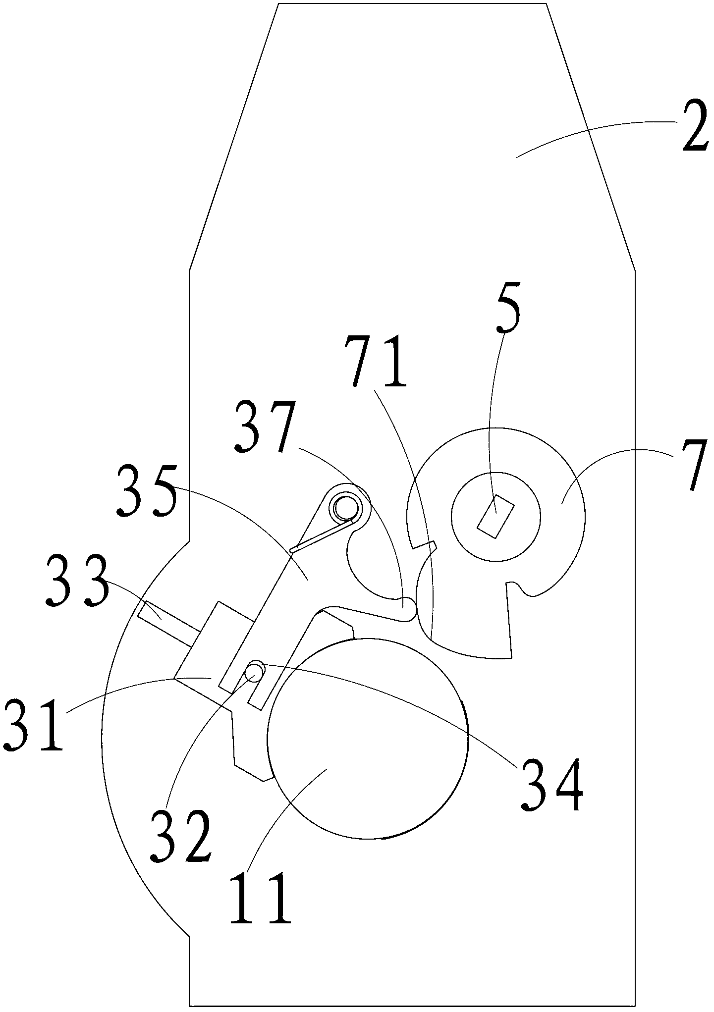
[0017] As shown in the accompanying drawings, a bottom mold unilateral locking mechanism, which is installed on the blow molding machine, includes a rotating shaft 5 that can rotate around its own axis, a power source that drives the rotating shaft 5 to rotate, and is fixed on the rotating shaft 5. The active connecting block 7, the driven connecting block 35 cooperating with the active connecting block 7, the slide block 31 that is slidably arranged in the horizontal direction, the bottom mold locking mechanism also includes a guide rail 33 that is arranged on the frame 2 in the horizontal direction, and the sliding The block 31 is slidably provided along the guide rail 33 .

[0018] Specifically, one end of the driven connection block 35 is rotationally connected to the frame 2, and the other end is connected to the slide block 31. The active connection block ...


PUM


Abstract

The invention discloses a bottom die single-side locking mechanism. The mechanism is arranged on a bottle blowing machine, and comprises a rotating shaft which can rotate around the axis, a power source which drives the rotating shaft to rotate, a driving connecting block which is fixedly arranged on the rotating shaft, a driven connecting block matched with the driving connecting block, and a slide block which is arranged along the horizontal direction in a sliding mode, wherein one end of the driven connecting block is rotationally connected with the frame, and the other end of the driven connecting block is connected with the slide block; and when the mechanism is in a die assembly state, a gap is formed between the bottom die and the frame, and the slide block is inserted into the gas and is pressed against the bottom die and the frame. By employing different locking structures, the volume of the equipment is reduced.

Description

technical field [0001] The invention relates to the field of beverage bottle processing equipment, in particular to a unilateral locking mechanism for a bottom mold of a bottle blowing machine. Background technique [0002] The bottle blowing machine in the prior art generally includes a frame, left and right molds and bottom molds arranged on the frame, and a driving mechanism and a positioning mechanism, such as the bottom mold of a linear blow molding machine disclosed in CN201755911U The locking device includes a mold mounting plate, a bottle mold cavity, a bottom mold, a power mechanism, a positioning mechanism and a support. On the support, the positioning mechanism includes a positioning block cylinder and a positioning block, the positioning block is connected to the positioning block cylinder, the power mechanism includes a bottom mold mounting plate and a bottom mold lifting cylinder, and the upper surface of the bottom mold mounting plate is connected to the botto...

Claims


Application Information

Patent Timeline
IPC IPC(8): B29C49/56B29L22/00
CPCB29C49/56B29C2049/566B29C33/20B29C33/26B29C2049/4892B29C49/5602B29C49/5608B29C49/5613B29C2049/5664
Inventor 董海龙杨夏英杨新良何德平
Owner JIANGSU NEWAMSTAR PACKAGING MACHINERY
Why Eureka
Try Eureka