Automobile brake pedal component

A technology of automobile brakes and components, applied in the direction of foot-operated starting devices, etc., can solve the problems of not satisfying the driver's operating habits and poor applicability, and achieve the effect of good applicability, high precision and stability, and ensuring driving safety

Active Publication Date: 2013-06-26
ZHEJIANG TAIHONG WANLI TECH CO LTD
View PDF6 Cites 9 Cited by
  • Summary
  • Abstract
  • Description
  • Claims
  • Application Information

AI Technical Summary

Problems solved by technology

Therefore, the automobile brake pedal in the above-mentioned patent cannot

Method used


Image

  • Automobile brake pedal component
  • Automobile brake pedal component
  • Automobile brake pedal component

Examples


Embodiment 1

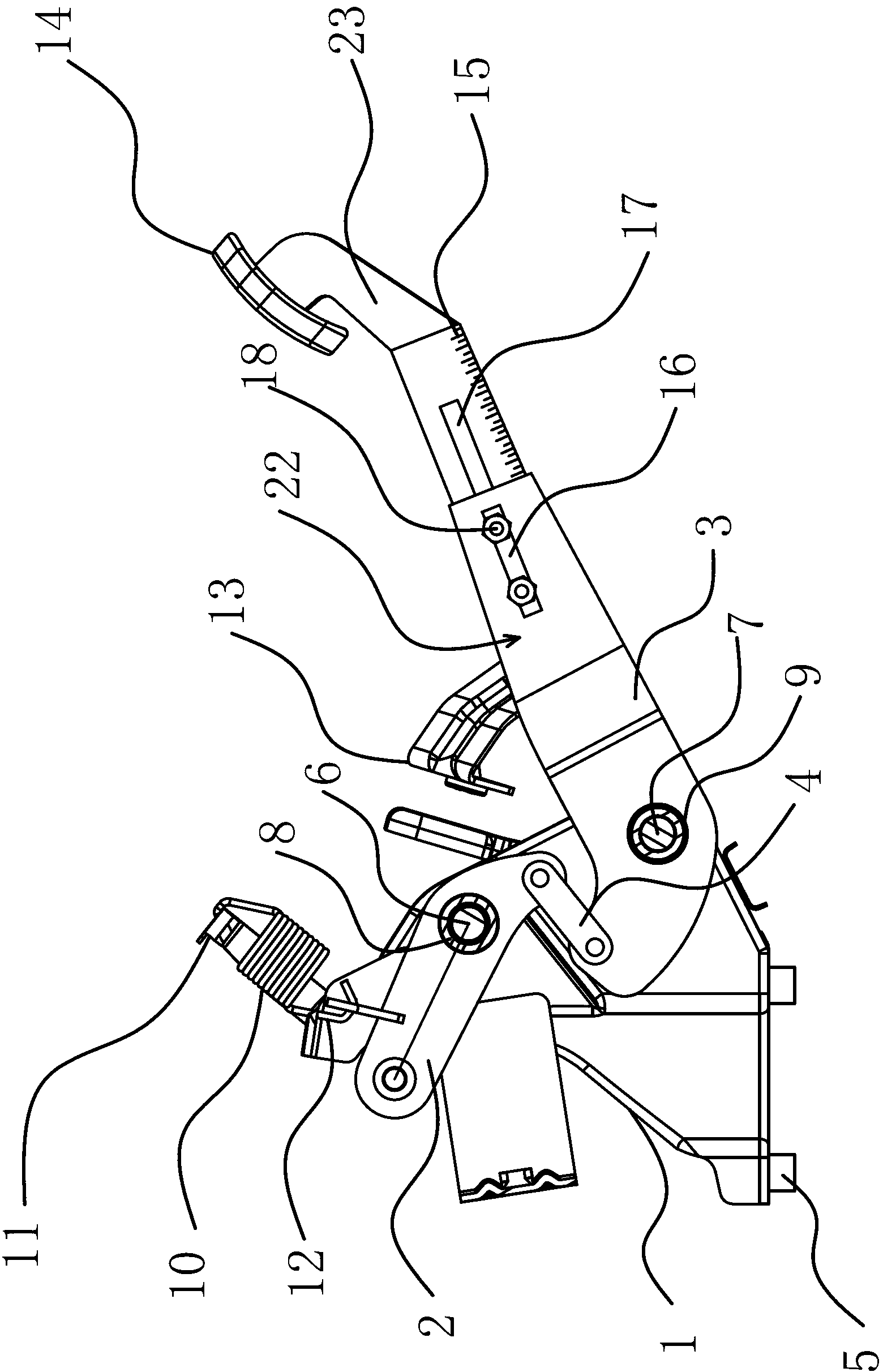
[0027] Such as figure 1As shown, the brake pedal assembly includes a mounting bracket 1, a driven arm 2, a force arm 3 and a connecting rod 4. Several metal bushings 5 ​​are welded on the bottom of the mounting bracket 1. When installing the brake pedal assembly, you can first The metal bushing 5 is set on the projection welding bolt at the fixed position of the front panel of the automobile body, and then locked with a nut, so that the assembly efficiency of the brake pedal assembly is high, and the assembly accuracy and firmness are correspondingly improved. Improvement; the installation bracket 1 is provided with a rotating shaft 1 6 and a rotating shaft 2 7, and a rubber bushing 1 8 and a rubber bushing 2 9 are set on the rotating shaft 6 and the rotating shaft 7 respectively, and the rubber bushing 1 8 and the rubber bushing Two 9 are fixed on the mounting bracket 1, the driven arm 2 and the force arm 3 are pivotally connected to the mounting bracket 1 through the rotatin...

Embodiment 2

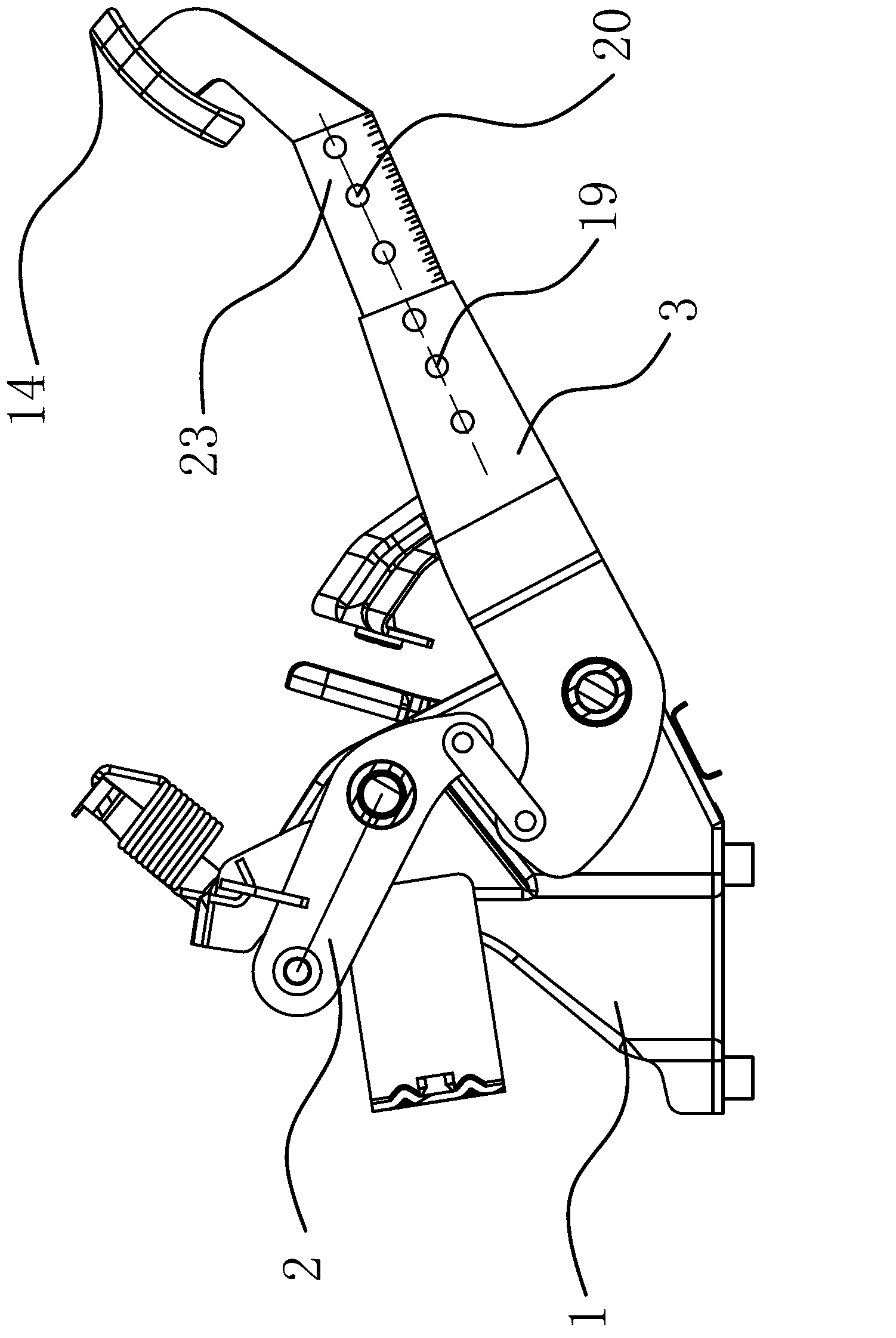
[0033] Such as figure 2 As shown, this embodiment is roughly the same as Embodiment 1, the difference is that the positioning structure 22 in this embodiment includes several positioning holes 19 opened on the force applying arm 3, and the positioning holes 19 are connected with the concave cavity Through and through both sides of the force applying arm 3, the positioning structure 22 also includes several positioning holes 20 opened on the telescopic arm 23, the positioning holes 20 run through both sides of the telescopic arm 23, and the positioning structure 22 also includes Several bolt assemblies that can pass through the first positioning hole 19 and the second positioning hole 20 at the same time. Through the cooperation of the bolt assembly with the first positioning hole 19 and the second positioning hole 20, the telescopic arm 23 and the force application arm 3 can be fixed together, and the bolt assembly is fast and convenient when loosening or tightening, and the ...

Embodiment 3

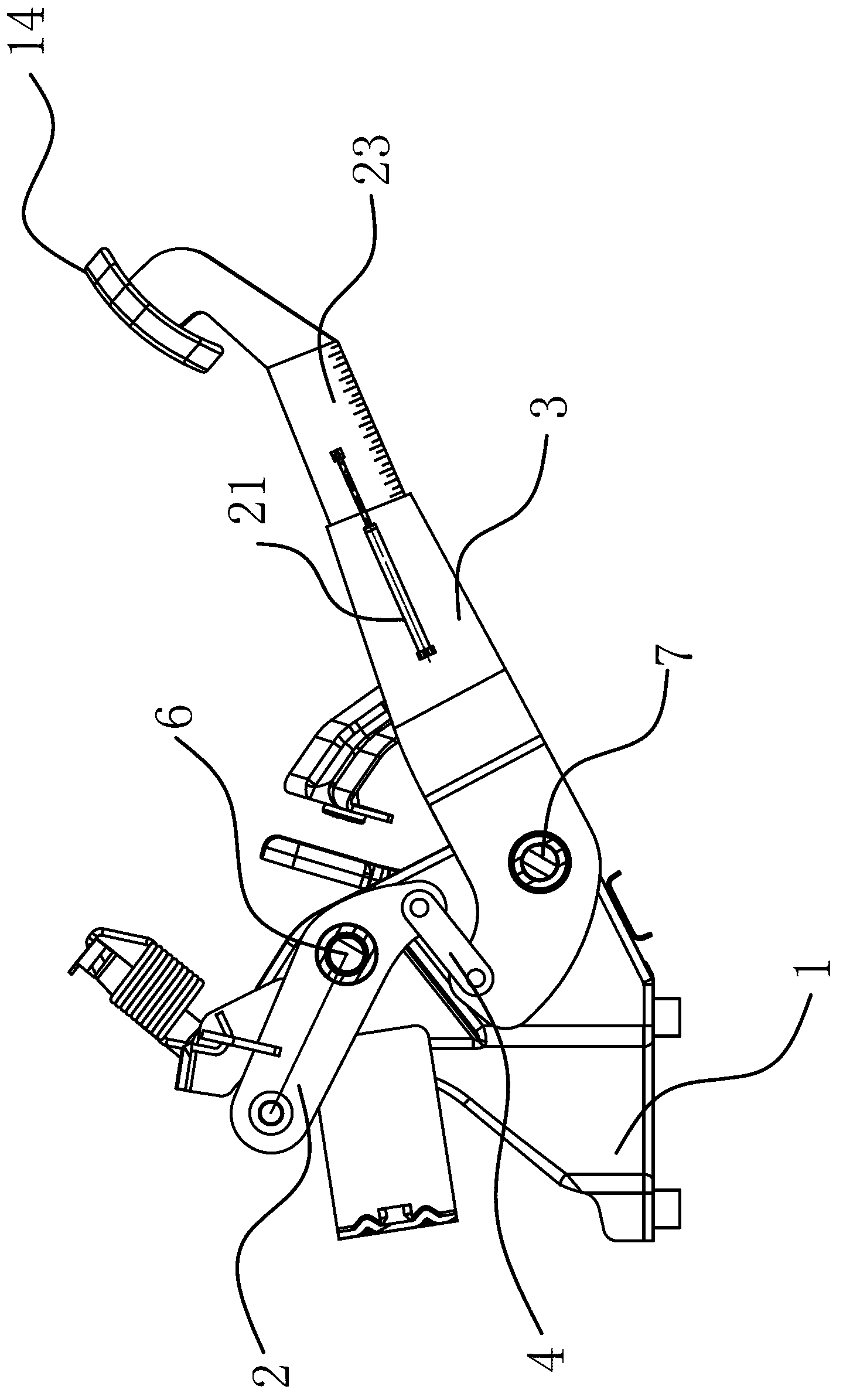
[0035] Such as image 3 As shown, this embodiment is roughly the same as Embodiment 1, the difference is that the positioning structure 22 in this embodiment includes a cylinder 21, and the two ends of the cylinder 21 are respectively fixed on the same side of the force applying arm 3 and the telescopic arm 23 , and the telescopic direction of the air cylinder 21 is consistent with the longitudinal direction of the telescopic arm 23 . After the cylinder 21 is designed, the telescopic arm 23 can be automatically retracted, and the brake pedal can be automated to a certain extent, reducing the driver's work intensity, while avoiding the driver's hand or clothing from being stained with oil when manually adjusting.


PUM


Abstract

The invention provides an automobile brake pedal component, and belongs to the technical field of automobile braking. The automobile brake pedal component solves the technical problems that an automobile brake pedal in the prior art is poor in applicability, and the like. The component comprises an installation support, a driven arm, a force application arm and a connection bar, wherein a first rotating shaft and a second rotating shaft are arranged on the installation support, the driven arm is connected on the installation support in a pivot mode through the first rotating shaft, the force application arm is connected on the installation support in a pivot mode through the second rotating shaft, a brake pump poking pork is connected at the outer end of the driven arm, the inner end of the driven arm is hinged with one end of the connection bar, and the other end of the connection bar is hinged with the inner end of the force application arm. The component further comprises a telescopic arm, a pedal plate is fixed at the outer end of the telescopic arm, the inner end of the telescopic arm is in sliding connection with the outer end of the force application arm, and a locating structure which enables the telescopic arm and the force application arm to be mutually fixed is arranged between the telescopic arm and the force application arm. The automobile brake pedal component has the advantages of being good in applicability, high in stability, and the like.

Description

technical field [0001] The invention belongs to the technical field of automobile brakes, and relates to an automobile brake pedal assembly. Background technique [0002] At present, as more and more female consumer groups join the ranks of car use, people's requirements for car driving comfort are constantly improving. The brake pedal is one of the most frequently used parts in the car. When the brake pedal is stepped on, due to the resistance of the brake pump, the deeper the step, the greater the resistance and the greater the stepping force. However, female drivers are relatively weak. When encountering an emergency, it is often difficult to step on the brake pedal to the maximum stroke, and cannot obtain the best braking effect, thereby adversely affecting safe driving. [0003] Chinese patent CN102442289A discloses a brake pedal for automobiles. The brake pedal includes a brake pedal swing arm, a first brake pedal rotation shaft, a triangular swing link, a second brak...

Claims


Application Information

Patent Timeline
IPC IPC(8): B60T7/06
Inventor 林礼德
Owner ZHEJIANG TAIHONG WANLI TECH CO LTD
Why Eureka
Try Eureka