
Launching and recovery device for self-government underwater vehicle

A technology for underwater vehicles and recovery devices, which is applied in the directions of transportation and packaging, ships, and load suspension components, etc., and can solve the difficulties in deploying and recovering autonomous underwater vehicles, operating personnel on small boats or even launching operations, Increase the risk of deployment and recovery to achieve the effect of protecting safety, ensuring reliability and reducing risk

Inactive Publication Date: 2013-06-26
SHENYANG INST OF AUTOMATION - CHINESE ACAD OF SCI
View PDF6 Cites 34 Cited by
  • Summary
  • Abstract
  • Description
  • Claims
  • Application Information

AI Technical Summary

Problems solved by technology

Due to the influence of sea wind and waves, the deployment and recovery of autonomous underwater vehicles has always been a relatively difficult operation process
At present, autonomous underwater vehicles mainly adopt the method of installing lifting points on the vehicle for deployment and recovery operations, but this method needs to separate the lifting points from the crane hook when deploying, and connect the lifting points to the hook when recovering. , it often requires staff to work on small boats or even launch them into the water, which increases the risk of deployment and recovery in bad sea conditions

Method used


Image

  • Launching and recovery device for self-government underwater vehicle
  • Launching and recovery device for self-government underwater vehicle
  • Launching and recovery device for self-government underwater vehicle

Examples


Embodiment Construction

[0018] The present invention will be described in further detail below in conjunction with the accompanying drawings.

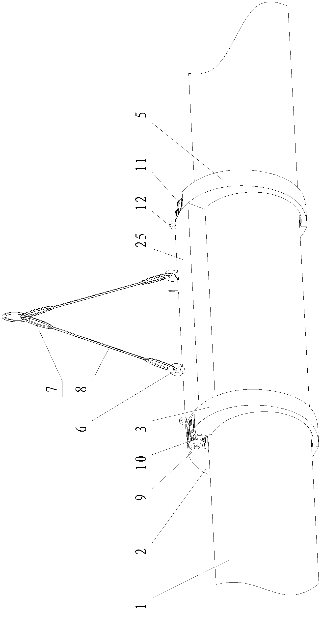
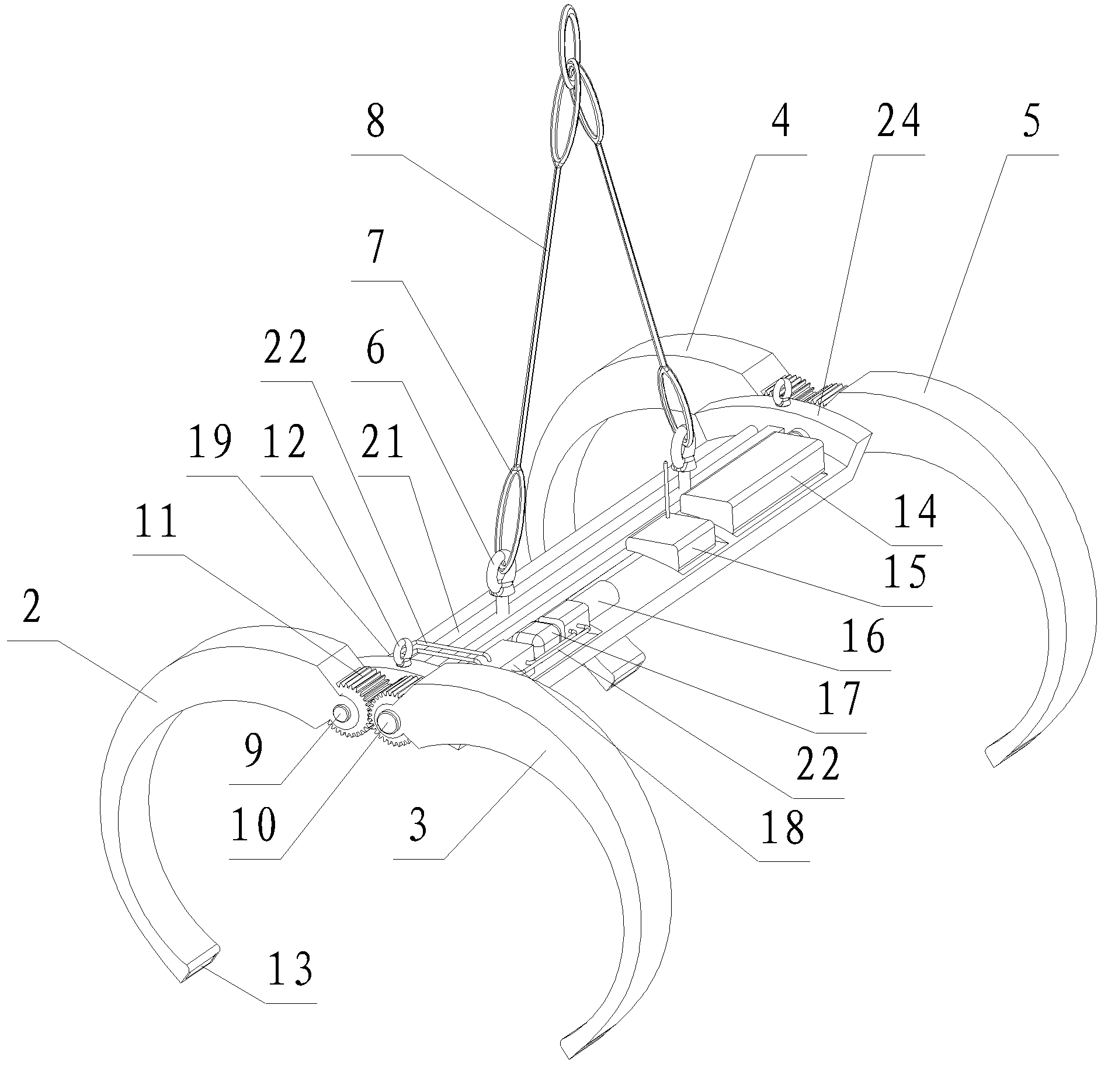
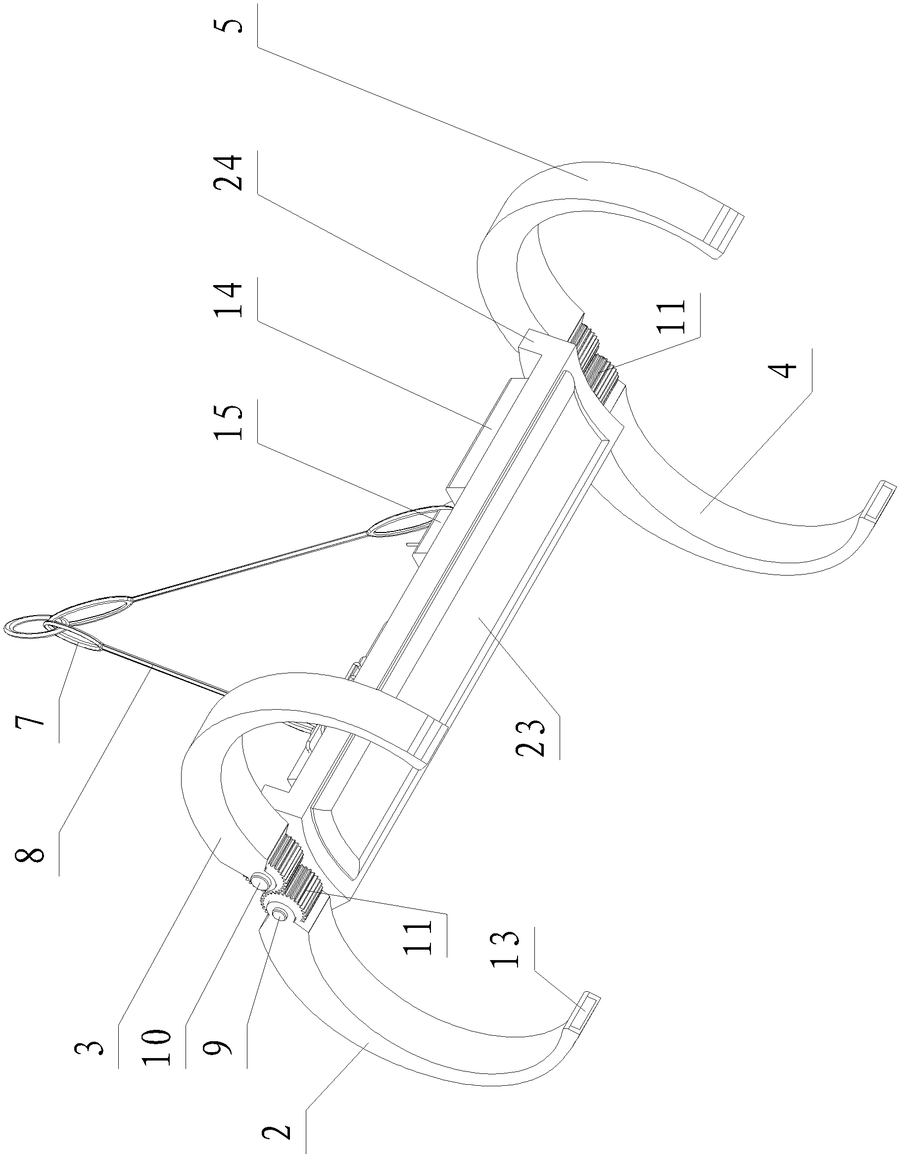
[0019] Such as Figure 1~3 As shown, the present invention includes a load-bearing beam body 24, a mechanical gripper, a lifting device, a battery module 14, a control and communication module 15 and a hydraulic system, wherein a protective cover 25 is installed on the load-bearing beam body 24, the battery module 14, control and communication modules The module 15 and the hydraulic system are installed on the load-bearing beam body 14 respectively, and both are located in the protective cover 25 . Both ends of the load-bearing beam body 24 are respectively provided with a mechanical gripper. The battery module 14 uses a high-density secondary lithium-ion battery to provide energy for the deployment and recovery device of the present invention. The control and communication module 15 and the hydraulic system are connected to the battery respectively. The mod...


PUM


Abstract

The invention belongs to the field of a self-government underwater vehicle, and particularly relates to a launching and recovery device for a self-government underwater vehicle. The launching and recovery device for the self-government underwater vehicle comprises a spandrel girder body, mechanical hands, a lifting device, a battery module, a control and communication module and a hydraulic system, wherein two ends of the spandrel girder body are respectively provided with the mechanical hand, the battery module is arranged on the spandrel girder body and provides power for the launching and recovery device, the control and communication module and the hydraulic system are respectively arranged on the spandrel girder and are respectively connected with the battery module, the control and communication module receives a control instruction sent from a worker on a mother ship, and the mechanical hands on the two ends are driven to synchronously open and close or clamp through the hydraulic system. According to the launching and recovery device for the self-government underwater vehicle, the self-government underwater vehicle can be launched and recovered by the worker on the mother ship, a mechanical recovery device capable of opening and closing autonomously is utilized so as to realize the launching and recovery process of the self-government underwater vehicle, so that the risk in the launching and recovery process of the self-government underwater vehicle is reduced.

Description

technical field [0001] The invention belongs to the field of autonomous underwater vehicles, in particular to a deploying and recovering device for autonomous underwater vehicles with the characteristic of a revolving body. Background technique [0002] An autonomous underwater vehicle is an underwater platform that relies on its own energy for autonomous navigation. Due to the influence of sea wind and waves, the deployment and recovery of autonomous underwater vehicles has always been a relatively difficult operation. At present, autonomous underwater vehicles mainly adopt the method of installing lifting points on the vehicle for deployment and recovery operations, but this method needs to separate the lifting points from the crane hook when deploying, and connect the lifting points to the hook when recovering. , It often requires staff to work on small boats or even launch them into the water, which increases the risk of deploying and recovering when the sea conditions ...

Claims


Application Information

Patent Timeline
IPC IPC(8): B63C7/16B66C1/10B66C13/20
Inventor 武建国于延凯徐会希郑荣王雷
Owner SHENYANG INST OF AUTOMATION - CHINESE ACAD OF SCI
Learn More