
Optical storage charging and discharging detection system and use method thereof

An optical storage and photovoltaic technology, applied in the direction of measuring devices, instruments, measuring electricity, etc., can solve the problems of power module multiplexing and power waste, and achieve the effects of improving power generation efficiency, flexible configuration, and improving module utilization

Inactive Publication Date: 2022-01-21
绿能慧充数字技术有限公司
View PDF0 Cites 0 Cited by
  • Summary
  • Abstract
  • Description
  • Claims
  • Application Information

AI Technical Summary

Problems solved by technology

[0003] Aiming at the problem that the charging module, the energy storage module and the photovoltaic module are mutually independent modules in the prior art, and the power module cannot be multiplexed and there is a waste of power, the present invention provides an optical storage charging and discharging inspection system and its use method. The organic combination of charging, discharging, electric vehicle battery detection, energy storage, and photovoltaics is integrated into a complete system. Through the organic combination of charging, discharging, electric vehicle battery detection, energy storage, and photovoltaics, new energy generation and electricity consumption are realized. , battery health detection

Method used


Image

  • Optical storage charging and discharging detection system and use method thereof
  • Optical storage charging and discharging detection system and use method thereof
  • Optical storage charging and discharging detection system and use method thereof

Examples


Embodiment 1

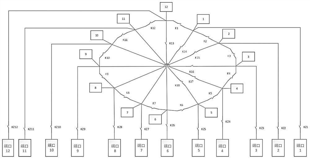
[0061] according to Figure 4 As shown, port 1 is equipped with an energy storage battery. When the electricity price is low, the first power module 1 is set as a bidirectional AC / DC module, the second power module 2, the third power module 3, the fourth power module 4, and the fifth The power module 5, the sixth power module 6, the seventh power module 7, the eighth power module 8, the ninth power module 9, the tenth power module 10, the eleventh power module 11 and the twelfth power module 12 are unidirectional AC / DC power conversion module, the bidirectional AC / DC module fully charges the energy storage battery. When the electricity price peaks, the energy storage battery releases the electric energy to the AC bus through the bidirectional AC / DC module, and the electric energy released to the AC bus can be passed through the second The power modules 2 to 12th power modules 12 and the automatic power distribution unit PCU charge the electric vehicles at other ports again, an...

Embodiment 2

[0064] according to Figure 5 As shown, port 1 is equipped with photovoltaics. When there is solar energy, the electric energy generated by photovoltaics can be distributed to other ports to charge electric vehicles through the PCU. The first power module 1 can also be set as a bidirectional AC / DC module, and the second power Module 2, third power module 3, fourth power module 4, fifth power module 5, sixth power module 6, seventh power module 7, eighth power module 8, ninth power module 9, tenth power module 10 . The eleventh power module 11 and the twelfth power module 12 are unidirectional AC / DC power conversion modules, which release the electric energy generated by photovoltaics to the grid or AC bus to supply power to other loads through the bidirectional AC / DC module;

[0065] When the power conversion module of a certain port is a bidirectional AC / DC module and is equipped with energy storage batteries and photovoltaics, the photovoltaic power generation can be used to...

Embodiment 3

[0067] Such as Figure 6 As shown, port 1 is equipped with energy storage battery + photovoltaic. When the electricity price is low, the first power module 1 is set as a bidirectional AC / DC module, the second power module 2, the third power module 3, the fourth power module 4, The fifth power module 5, the sixth power module 6, the seventh power module 7, the eighth power module 8, the ninth power module 9, the tenth power module 10, the eleventh power module 11 and the twelfth power module 12 are The one-way AC / DC power conversion module fully charges the energy storage battery through the two-way AC / DC module. When the electricity price peaks, the energy storage battery releases the electric energy to the AC bus through the two-way AC / DC module, and the electric energy released to the AC bus can be The electric vehicles at other ports are charged again through the second power module 2 to the twelfth power module 12 and the automatic power distribution unit PCU. When the ba...


PUM


Abstract

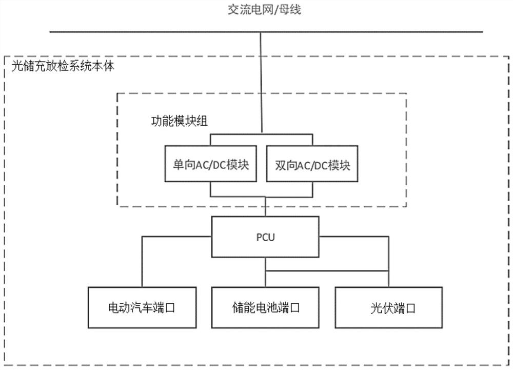
The invention provides an optical storage charging and discharging detection system and a use method thereof. The optical storage charging and discharging detection system body is connected with an alternating current power grid, and the optical storage charging and discharging detection system body organically combines charging, discharging, electric vehicle battery detection, energy storage and photovoltaic, so that charging and discharging of the electric vehicle and the battery detection of the electric vehicle are realized, solar energy can be stored in an energy storage battery, and the energy storage battery discharges electricity to the electric vehicle or other loads of a power grid; or the solar energy can be directly supplied to the electric vehicle, or the solar energy is connected to the grid. A plurality of groups of power can be effectively and automatically distributed to any one port through the power automatic distribution unit PCU, a bidirectional AC / DC module is added to the functional module group, the reuse of a power supply is effectively improved, and power generation, power utilization and battery health degree detection of new energy are realized through organic combination of charging, discharging, electric vehicle battery detection, energy storage and photovoltaic.

Description

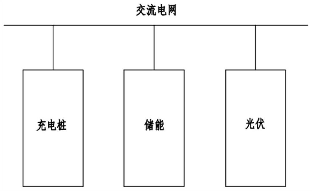
technical field [0001] The invention relates to the technical field of power electronics, in particular to an optical storage charging and discharging inspection system and a method for using the same. Background technique [0002] Charging piles, energy storage, and photovoltaics are all mature products in the market. Generally, the three products are independent of each other, such as figure 1 As shown, the three are coupled at the AC grid. The energy storage battery is charged when the electricity price is low, and stores energy. When the electricity price peaks or there is demand, the stored energy is converted into alternating current through the DC / AC conversion module of the energy storage system and returned to the grid. After the energy returns to the grid, it can be directly supplied to electric vehicles or other loads through the AC / DC module of the charging pile. When photovoltaics have solar energy, they can be converted into alternating current through the DC...

Claims


Application Information

Patent Timeline
IPC IPC(8): G01R31/392
CPCG01R31/392
Inventor 侯宁李恩虎赵青
Owner 绿能慧充数字技术有限公司
Learn More