Transport container and floor thereof

A container and bottom structure technology, applied in the direction of transportation and packaging, packaging, construction, etc., to achieve the effect of reducing maintenance work, reducing thickness, obvious transportation and cost advantages

Inactive Publication Date: 2013-06-26
RAUTARUUKKI
View PDF8 Cites 1 Cited by
  • Summary
  • Abstract
  • Description
  • Claims
  • Application Information

AI Technical Summary

Problems solved by technology

[0004] It is therefore an object of the present invention to provide a bottom structure for a transport container and a transport container which solve or at least alleviate the above-mentioned problems

Method used


Image

  • Transport container and floor thereof
  • Transport container and floor thereof
  • Transport container and floor thereof

Examples


Embodiment Construction

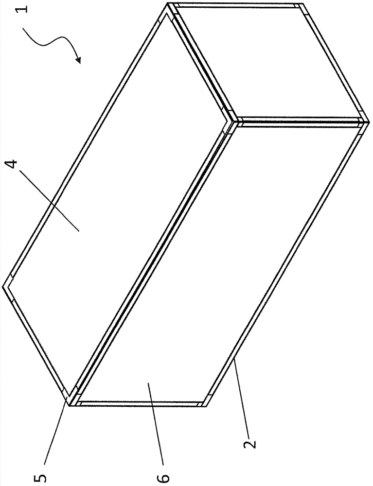
[0014] figure 1 A general purpose transport container 1 for transporting dry goods is schematically shown. The transport container 1 is substantially rectangular and comprises a wall structure 6 , a top structure 4 and a bottom structure 2 . The container 1 also comprises a support frame 5 supporting the wall structure, the roof structure and the bottom structure. The container 1 is also provided with a loading door (not shown). The wall structure 6 and the roof structure 4 are generally formed from steel profiles which may be coated with zinc and / or paint or some other coating material.

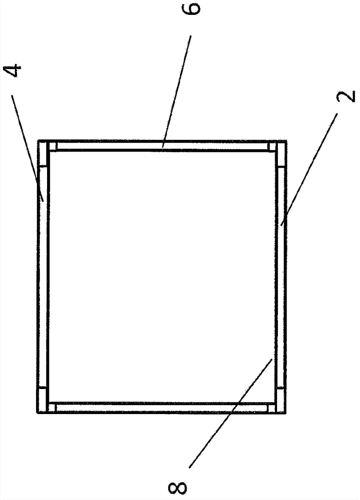
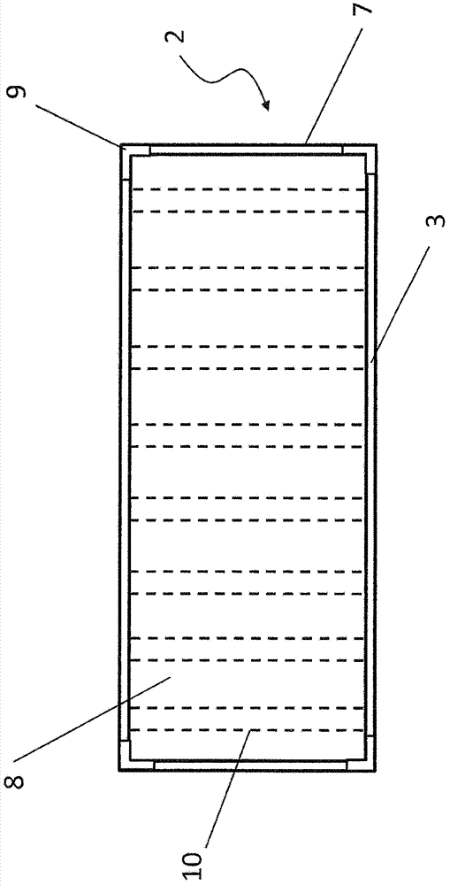
[0015] Figure 2A The transport container 1 is shown from one end. It can be seen that the supporting frame together with the top structure 4 , the wall structure 6 and the bottom structure 2 form a substantially rectangular cargo space. The bottom structure 2 comprises a first surface layer 8 forming the bottom surface of the cargo space of the container 1 . Figure 2B The bottom stru...


PUM


Abstract

The present invention relates to a floor structure (2) for a transport container (1) and to the transport container. The floor structure (2) comprises a first surface layer (8) forming a floor surface and support arrangements (10, 11, 24) for supporting the first surface layer (8). According to the present invention, the first surface layer (8) is formed from hardened martensitic steel sheet.

Description

technical field [0001] The present invention relates to a floor structure for a transport container, more particularly to a floor structure according to the preamble of claim 1 . The invention further relates to a transport container, more particularly to a transport container according to the preamble of claim 16 . Background technique [0002] Shipping containers, as well as so-called universal shipping containers or dry shipping containers, are used to transport a wide variety of goods. A conventional shipping container includes a support frame and a base structure, a wall structure and a roof structure attached to and supported by the support frame. The substructure generally comprises independent support beams attached to the support frame such that these support beams extend in a transverse direction with respect to the longitudinal direction of the substructure. The supporting frame is usually formed from tubular members and the supporting beams are formed from I-be...

Claims


Application Information

Patent Timeline
Patent Type & Authority Applications(China)
IPC IPC(8): B65D90/12B65D88/12B65D90/02
CPCB65D90/02B65D88/12E04B5/00
Inventor 伊尔波·马拉宁尤卡·西尔塔宁维莱-马蒂·努尔梅拉
Owner RAUTARUUKKI
Why Eureka
Try Eureka