Variable electro-hydraulic servo hydraulic transformer

A hydraulic transformer and electro-hydraulic servo technology, applied in fluid pressure converters, fluid pressure actuation devices, fluid pressure actuation system components, etc., can solve load pressure and load flow coupling, load flow is uncontrollable, and cannot be generalized and other issues to achieve the effect of low power loss

Active Publication Date: 2015-06-24
HARBIN INST OF TECH
View PDF6 Cites 0 Cited by
  • Summary
  • Abstract
  • Description
  • Claims
  • Application Information

AI Technical Summary

Problems solved by technology

[0004] The purpose of the present invention is to solve the problem that the load pressure of the existing hydraulic transformer is controllable but the load flow is uncontrollable or the load pressure and the load flow are coupled, and the problem that hydraulic transformers with different specifications are required for different occasions cannot be generalized, and then Provide a variable electro-hydraulic servo hydraulic transformer

Method used


Image

  • Variable electro-hydraulic servo hydraulic transformer
  • Variable electro-hydraulic servo hydraulic transformer
  • Variable electro-hydraulic servo hydraulic transformer

Examples


specific Embodiment approach 1

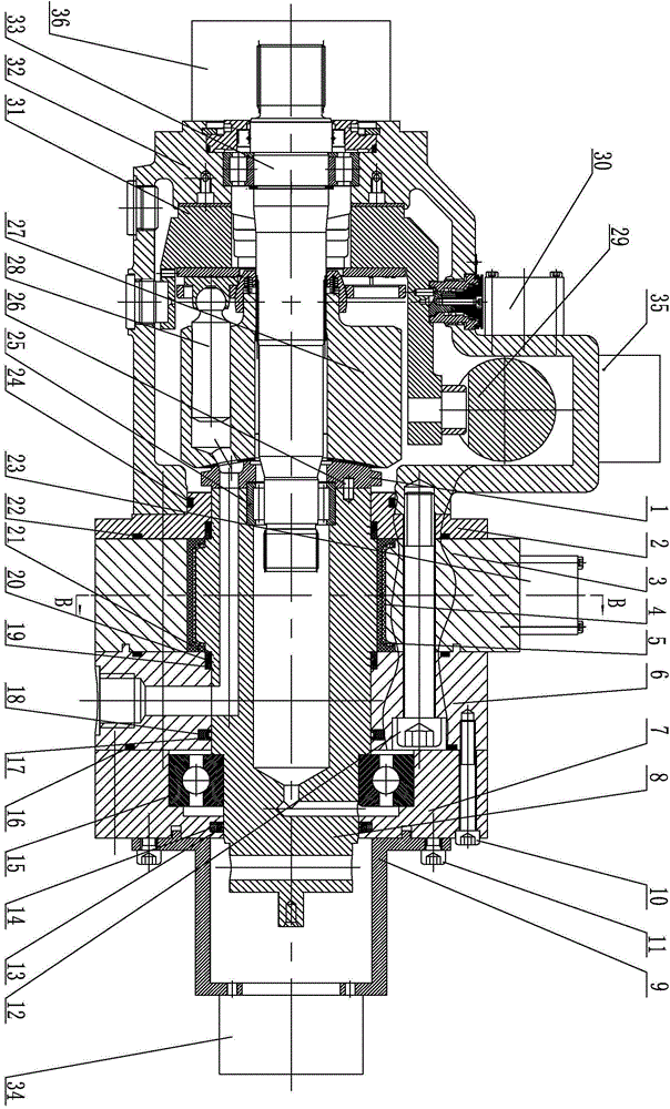
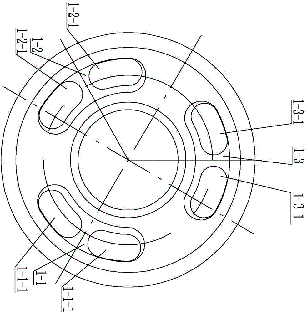
[0017] Specific implementation mode one: combine Figure 1 to Figure 8 Describe this embodiment, a variable electro-hydraulic servo hydraulic transformer in this embodiment includes a valve plate servo mechanism and a swash plate servo mechanism;

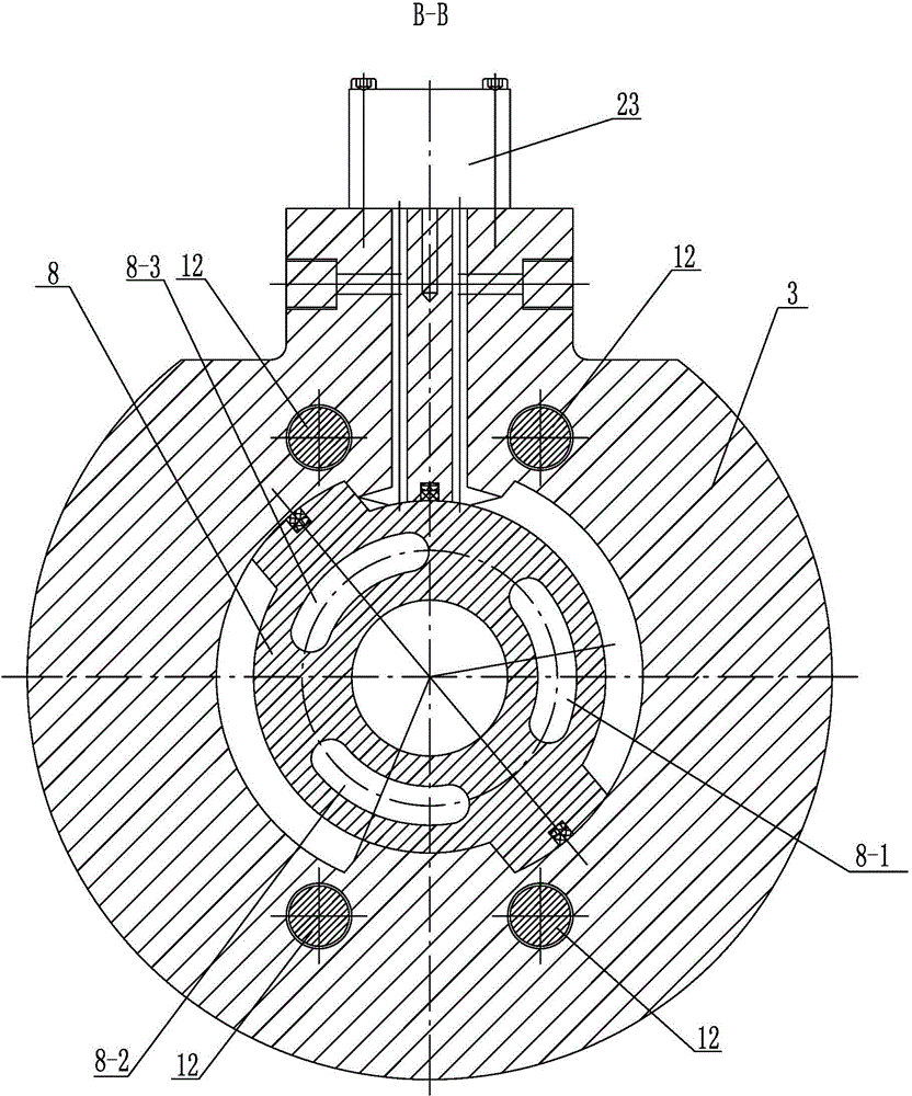
[0018] The valve plate servo mechanism includes a valve plate 1, an end cover 2, a valve housing 6, a bearing cover 7, a bearing 15, a first hydraulic control valve 23 and a swing motor, and the swing motor includes a motor housing 3 and a vane shaft 8 , the distribution plate 1 is detachably connected to the vane shaft 8, the motor housing 3 is arranged between the end cover 2 and the distribution housing 6 and the three are detachably connected, the vane shaft 8 is penetrated in the inner cavity of the motor housing 3 and The two contact and seal, one end of the vane shaft 8 is detachably connected with the distribution plate 1, and the other end of the vane shaft 8 is supported and rotated by the bearing 15 installed on the beari...

specific Embodiment approach 2

[0024] Specific implementation mode two: combinationfigure 1 To illustrate this embodiment, the hydraulic transformer in this embodiment further includes a first screw 12 , and the motor casing 3 , the end cover 2 , the distribution casing 6 and the casing 32 are detachably connected by the first screw 12 . With such arrangement, the installation and disassembly are convenient, and the use is convenient. Others are the same as in the first embodiment.

specific Embodiment approach 3

[0025] Specific implementation mode three: combination figure 1 To illustrate this embodiment, the hydraulic transformer in this embodiment further includes a second screw 10 , and the bearing cover 7 is detachably connected to the distribution housing 6 through the second screw 10 . With such arrangement, the installation and disassembly are convenient, and the use is convenient. Others are the same as in the first or second embodiment.


PUM


Abstract

The invention provides a variable electro-hydraulic servo hydraulic transformer, and relates to an electro-hydraulic servo hydraulic transformer which resolves the problems that an existing hydraulic transformer is controllable in loading pressure and uncontrollable in loading flow, alternatively, the loading pressure and the loading flow are coupled, hydraulic transformers of different standards need to be applied to different areas, and universalization is not achieved. The variable electro-hydraulic servo hydraulic transformer comprises a thrust plate servo mechanism and a swash plate servo mechanism, the valve plate servo mechanism comprises a thrust plate, an end cover, a thrust shell, a bearing cover, a bearing, a first hydraulic control valve and a swing motor, the thrust plate is in detachable connection with a blade shaft, a motor shell is arranged between the end cover and the thrust shell and in detachable connection with the end cover and the thrust shell, and the first hydraulic control valve is arranged on the motor shell. The swash plate servo mechanism comprises a cylinder, a hydraulic cylinder, a second hydraulic control valve, a swash plate, a shell, a transmission shaft and a plurality of plungers, wherein the shell is in detachable connection with the end cover. The variable electro-hydraulic servo hydraulic transformer is used for a system control valve of the hydraulic field.

Description

technical field [0001] The invention relates to an electro-hydraulic servo hydraulic transformer, in particular to a variable power control element with low power loss. Background technique [0002] Hydraulic transformers refer to components that mainly realize pressure changes in the hydraulic field. The CPR (Common Pressure Rail) system is a new platform built by the hydraulic industry. This technology is similar to the grid technology in the power system, which can greatly improve the efficiency of the hydraulic system, reduce the number of power sources, further simplify the structure of the hydraulic system and reduce the cost of use. The current research work of this technology is mainly aimed at the two aspects of the control strategy of the components in the CPR system and the components themselves. The hydraulic transformer is one of the components in the CPR system, and its research is currently in its infancy. The hydraulic transformer can be applied not only to...

Claims


Application Information

Patent Timeline
Patent Type & Authority Patents(China)
IPC IPC(8): F15B3/00F15B21/08
Inventor 姜继海杨冠中
Owner HARBIN INST OF TECH
Why Eureka
Try Eureka