Servo hydraulic cylinder

A technology of hydraulic oil cylinder and cylinder body, applied in the field of hydraulic oil cylinder, can solve the problems of decreased sealing effect, loss of sealing performance, leakage of hydraulic oil, etc., and achieve the effect of enhancing sealing effect, prolonging service life and reducing relative friction

Active Publication Date: 2013-06-26
韶关市伟光液压油缸有限公司
View PDF5 Cites 11 Cited by
  • Summary
  • Abstract
  • Description
  • Claims
  • Application Information

AI Technical Summary

Problems solved by technology

[0002] In the servo hydraulic cylinder of the prior art, the piston rod is in direct contact with the guide sleeve. During operation, due to long-term friction between the piston rod and the guide sleeve, wear problems are prone to occur, especially under high-speed reciprocating motion, such as reciprocating motion under 200HZ. The wear between the piston rod and the guide sleeve is more serious, resulting in a decrease in the working efficiency of the servo hydraulic cylinder or even a breakdown
At the same time, the first seal between the piston rod and the guide sleeve can directly contact the hydraulic oil in the cylinder body. During the operation of the servo hydraulic cylinder, it will be subjected to the force of the hydraulic oil. The first seal is in a high-pressure working environment. It is prone to wear, heat and even damage, resulting in a decrease in sealing effect or even loss of sealing performance, and the problem of hydraulic oil leakage, which reduces the working efficiency of the servo hydraulic cylinder and shortens the service life of the servo hydraulic cylinder

Method used


Image

  • Servo hydraulic cylinder
  • Servo hydraulic cylinder

Examples


Embodiment Construction

[0022] The present invention will be described in further detail below in conjunction with the accompanying drawings.

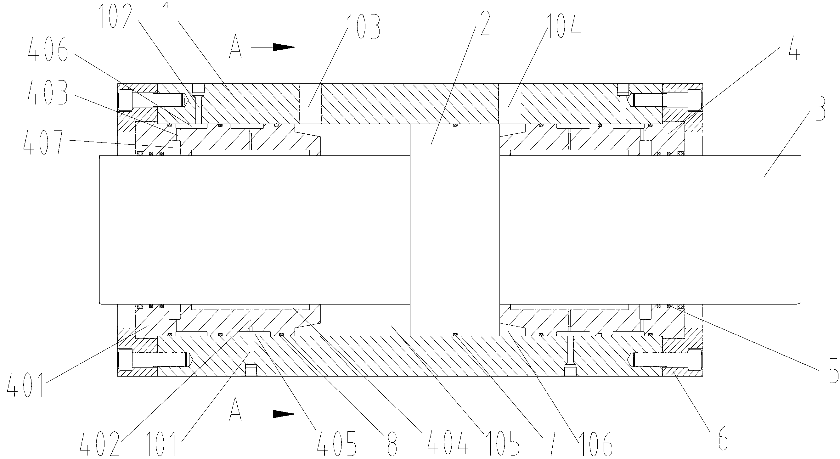
[0023] figure 1 A servo hydraulic cylinder according to an embodiment of the present invention is schematically shown. Such as figure 1 As shown, the servo hydraulic cylinder includes a cylinder body 1 , a piston 2 , a piston rod 3 , a pair of guide sleeves 4 , and a first seal 5 . In addition, a pair of end caps 6 , a second seal 7 and a third seal 8 are also included.

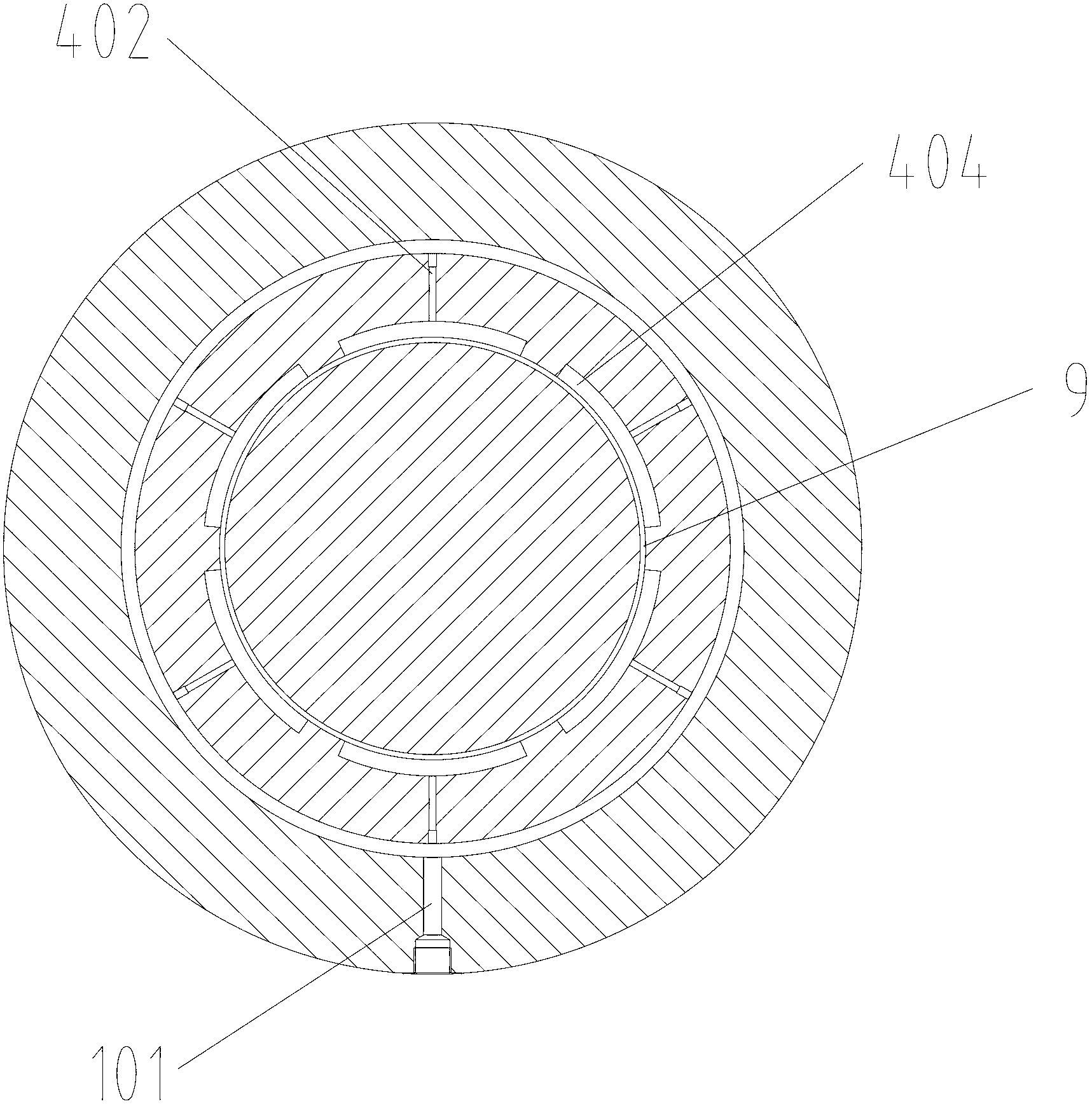
[0024] A first oil injection hole 101 , a first oil drain hole 102 , a first oil through hole 103 and a second oil through hole 104 are provided on the outer surface of the cylinder body 1 and communicate with the inner cavity. The piston 2 is built into the inner cavity of the cylinder body 1 , and its outer surface is in close contact with the inner wall of the cylinder body 1 , separating the inner cavity of the cylinder body 1 into an independent first oil holding chamber 105 and a se...


PUM


Abstract

The invention discloses a servo hydraulic cylinder. The servo hydraulic cylinder comprises a cylinder body, a piston, a piston rod, a pair of guide sleeves and a first sealing element. A first oil drainage hole and a first oil filling hole communicated with a cylinder body cavity are formed in the outer surface of the cylinder body. The piston is arranged inside the cylinder body cavity and capable of doing axial reciprocating motion, and separates the cylinder body into two independent parts. The piston rod is fixedly connected with the piston. Two ends of the piston rod penetrate out two ends of the cylinder body. The pair of guide sleeves are arranged at two ends of the cylinder body and sleeved on the piston rod. The pair of guide sleeves are provided with second oil filling holes and second oil drainage holes. The second oil filling holes are communicated with the first oil filling holes. The second oil drainage holes are communicated with the first oil drainage holes. An oil sealing surface is formed between the inner wall of the guide sleeve and the outer surface of the piston rod. The first sealing element is arranged between the outer surface of the piston rod and the inner wall of the guide sleeve. The oil sealing surface separates the first sealing element and the cylinder body cavity. The servo hydraulic cylinder has the advantages of being capable of effectively reducing abrasion between the piston rod and the guide sleeve, stable in sealing, and long in service life.

Description

technical field [0001] The invention relates to a hydraulic oil cylinder, in particular to a servo hydraulic oil cylinder. Background technique [0002] In the servo hydraulic cylinder of the prior art, the piston rod is in direct contact with the guide sleeve. During operation, due to long-term friction between the piston rod and the guide sleeve, wear problems are prone to occur, especially under high-speed reciprocating motion, such as reciprocating motion under 200HZ. The wear between the piston rod and the guide sleeve is more serious, resulting in a reduction in the working efficiency of the servo hydraulic cylinder or even a breakdown. At the same time, the first seal between the piston rod and the guide sleeve can directly contact the hydraulic oil in the cylinder body. During the operation of the servo hydraulic cylinder, it will be subjected to the force of the hydraulic oil. The first seal is in a high-pressure working environment. It is prone to wear, heat and e...

Claims


Application Information

Patent Timeline
Patent Type & Authority Applications(China)
IPC IPC(8): F15B15/14F15B15/20
Inventor 陈伟光王京兴
Owner 韶关市伟光液压油缸有限公司
Why Eureka
Try Eureka