

Diaphragm valve with adjustable pressure and adjustable flow range
A flow range, diaphragm valve technology, applied in the direction of valve details, valve device, valve operation/release device, etc., can solve the problems of less technical disclosure, etc., to achieve wide application, simple and practical structure, significant economic and social benefits Effect
- Summary
- Abstract
- Description
- Claims
- Application Information
AI Technical Summary
Problems solved by technology
Method used
Image

Examples
Embodiment 1
[0020] Example 1: As attached figure 1 As shown, a front pressure sensor 7 is installed at the liquid inlet in the valve chamber 12, or a rear pressure sensor 14 is installed at the liquid outlet in the valve chamber 12. The front pressure sensor 7 or the rear pressure sensor 14 is connected to the valve signal processing unit 13 A control unit 15 is installed on the valve body 1. The control unit 15 is connected to the control chamber 6 through a control chamber connecting pipe 18. The control unit 15 is connected to the inlet of the valve chamber 12 through a water source pipe 16, and the control unit 15 is also connected to a discharge pipe 17 is connected, and at the same time, the control unit 15 and the valve signal processing unit 13 are electrically connected.
[0021] In the foregoing, there is a valve cavity 12 inside the valve body 1, the upper side of the valve cavity 12 is equipped with a valve core 2, the upper part of the valve body 1 has a neck shell 4, and the upp...
Embodiment 2
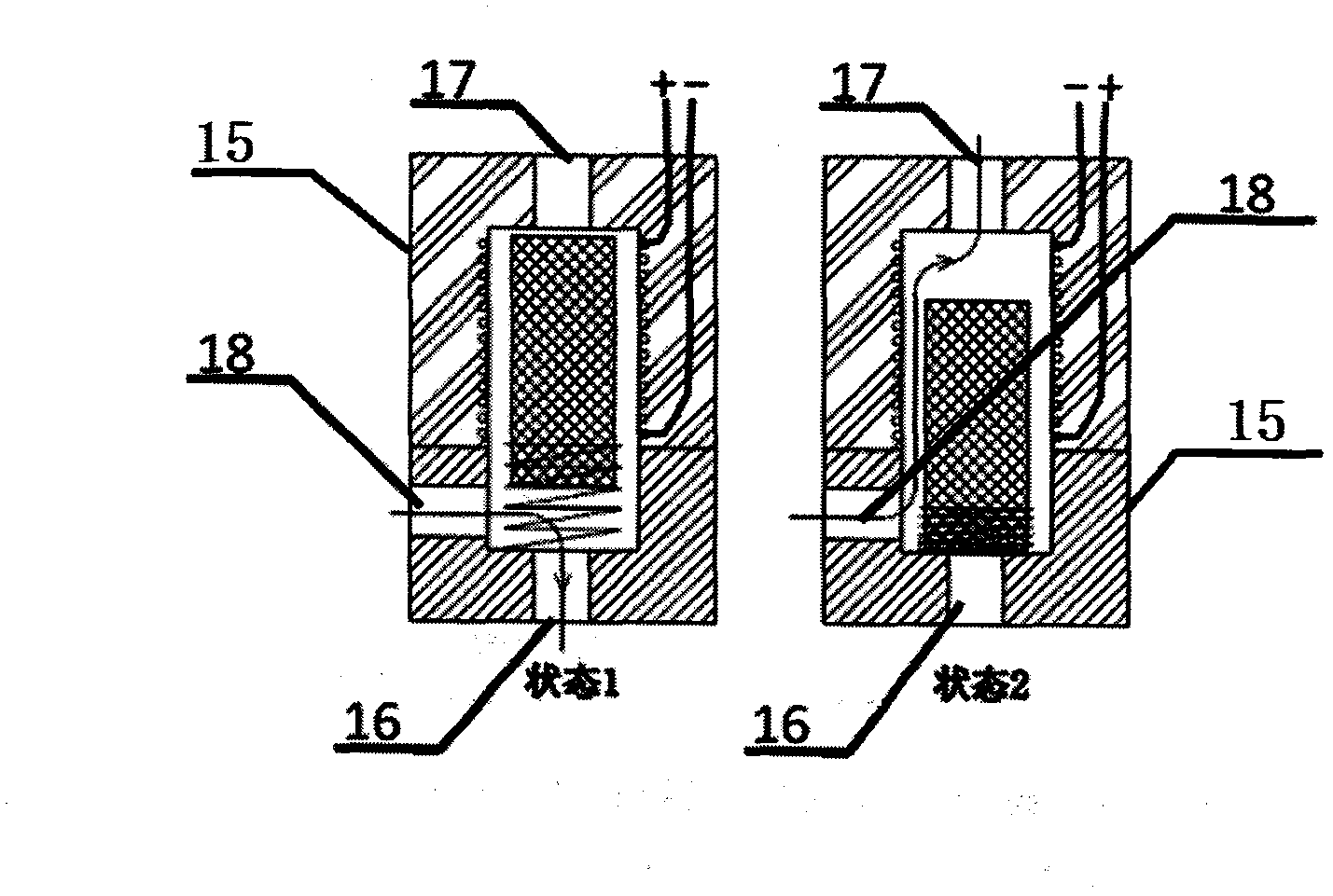
[0034] Example 2: In Example 1, especially as attached image 3 As shown, the pipeline conversion structure of the control unit 15 includes an internal cavity and a conversion core installed in the internal cavity. The internal cavity is respectively connected with the water source tube 16, the discharge tube 17 and the control cavity connecting tube 18, especially the middle of the conversion core The hinge is mounted on the wall of the inner cavity. At the same time, the water source pipe 16, the discharge pipe 17 and the control cavity connecting pipe 18 are connected to the inner cavity side by side on the same side. The central hinge point of the conversion core is located at the interface of the control cavity connecting pipe 18 in the inner cavity. On the axis, the control cavity connecting pipe 18 is normally open, and the conversion core has a blocking surface on both sides of the hinge point, and the two blocking surfaces respectively cooperate with the water source pip...
Embodiment 3
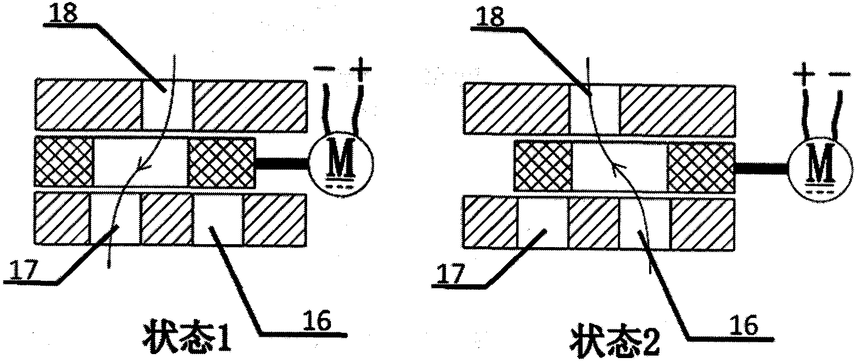
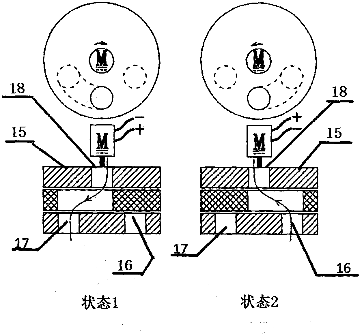
[0035] Example 3: In Example 1, especially as attached Figure 4 As shown, the piping conversion structure of the control unit 15 is coaxially installed to connect the connecting plate of the control cavity connecting pipe 18, the hollowed-out conversion core and the socket connected to the water source pipe 16 and the discharge pipe 17. The conversion core is installed with electromagnetic Action device. When working, in state 1, through the action of electromagnetic force, the conversion core rotates to block the interface of the water source pipe 16, then the tube 18 is connected through the pipeline hollowed out from the center of the conversion core to the discharge pipe 17; in the state 2, through The electromagnetic force acts, the conversion core rotates and blocks the interface of the discharge pipe 17, and the water source pipe 16 is hollowed out through the middle of the conversion core to the control cavity connecting pipe 18 to conduct.
PUM
 Abstract
Description
Claims
Application Information