
Light-emitting diode (LED) backlight driving circuit and backlight module

A backlight drive circuit and drive unit technology, applied in the semiconductor field, can solve the problems of unfavorable cost reduction, high MOS tube temperature, and high MOS tube price, and achieve the effect of safe and reliable LED short circuit protection function

Active Publication Date: 2013-06-26
SHENZHEN CHINA STAR OPTOELECTRONICS TECH CO LTD
View PDF10 Cites 36 Cited by
  • Summary
  • Abstract
  • Description
  • Claims
  • Application Information

AI Technical Summary

Problems solved by technology

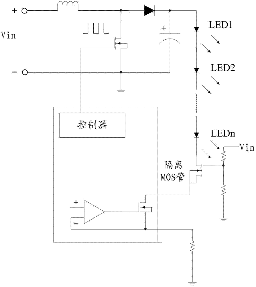
[0005] Although the MOS tube can protect the LED backlight drive circuit, when the LED backlight drive circuit is working normally, the MOS tube is turned on, and the power loss in the MOS tube is large, and the temperature of the MOS tube is high, which affects its life. The price of MOS tubes is also high, which is not conducive to cost reduction
In addition, when the MOS tube is disconnected, there is still a high voltage on the negative pole of the LED, which will cause certain safety hazards

Method used


Image

  • Light-emitting diode (LED) backlight driving circuit and backlight module
  • Light-emitting diode (LED) backlight driving circuit and backlight module
  • Light-emitting diode (LED) backlight driving circuit and backlight module

Examples


Embodiment Construction

[0021] The present invention will be described in detail below with reference to the drawings and embodiments.

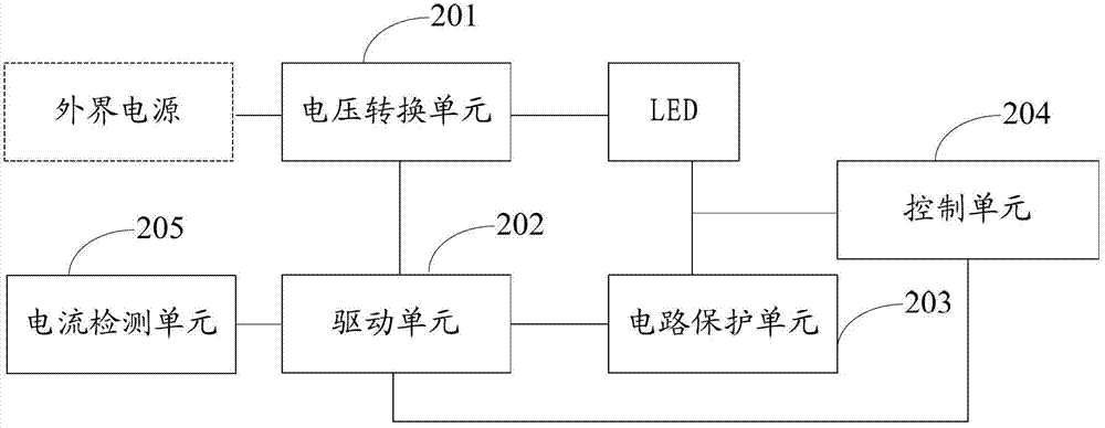
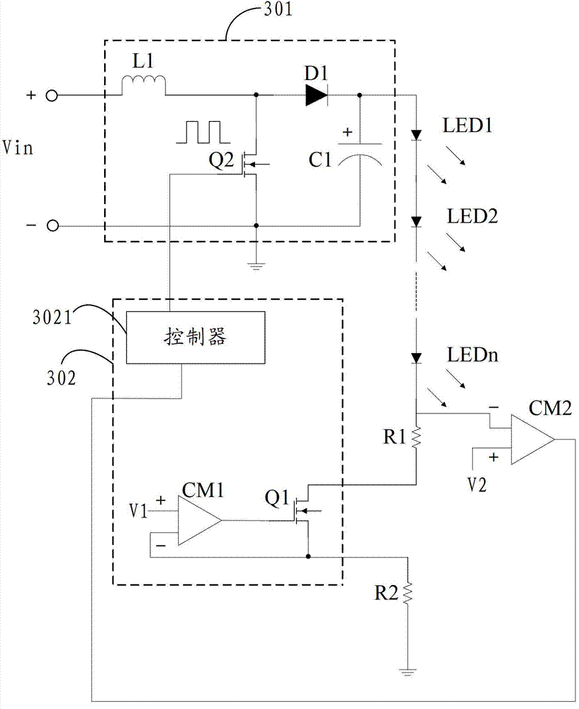
[0022] refer to figure 2 , in an embodiment of the LED backlight driving circuit of the present invention, it includes a voltage conversion unit 201 , a driving unit 202 , a protection unit 203 , a control unit 204 and a current detection unit 205 . Wherein, the voltage conversion unit 201 includes an input terminal, an output terminal and a controlled terminal, the input terminal of which is used to connect the output terminal of an external power supply, and the output terminal of the voltage conversion unit 201 is used to connect the anode of the LED to provide driving voltage for the LED. The drive unit 202 includes an output terminal and three input terminals, and its output terminal is connected to the controlled terminal of the voltage conversion unit 201, and is used to drive the voltage conversion unit 201 to realize voltage conversion, so that the voltage...


PUM


Abstract

The invention discloses a light-emitting diode (LED) backlight driving circuit and a backlight module. According to the LED backlight driving circuit, a voltage conversion unit is used for converting the output voltage of an external power supply into driving voltage required by an LED; an output end of the voltage conversion unit is connected to an anode of the LED and used for supplying the required driving voltage to the LED; a driving unit is used for controlling the voltage conversion unit to realize voltage conversion; a circuit protection unit is connected in series between a cathode of the LED and the driving unit; the maximum allowable power of the circuit protection unit is smaller than power borne by the circuit protection unit when the driving voltage of the LED is directly applied to the circuit protection unit; and a control unit outputs an operation stopping control signal to the driving unit when the circuit protection unit is open-circuited. In the mode, a circuit device can be protected from being damaged, so an LED short-circuit protection function is safe and reliable.

Description

technical field [0001] The invention relates to the technical field of semiconductors, in particular to an LED backlight driving circuit and a backlight module. Background technique [0002] The LCD display panel itself cannot generate a light source, and it must use a backlight to project light onto the display panel to generate brightness on the display panel, and the brightness must be evenly distributed to obtain an image display. At present, the backlight source of the LCD display panel is mainly divided into two types: LED and CCFL. Compared with CCFL backlight, LED backlight has the advantages of low power consumption, long life, ultra-thin and good optical characteristics. Therefore, liquid crystal display with white LED as backlight is gradually becoming the development direction of LCD TV. [0003] In order to ensure the performance of the LED backlight module and avoid failure of the LED backlight module to cause the liquid crystal display to fail to display, the...

Claims


Application Information

Patent Timeline
IPC IPC(8): G09G3/34H05B44/00
CPCG09G3/3406G09G2330/04Y02B20/30H05B45/38G09G3/34
Inventor 张华张先明
Owner SHENZHEN CHINA STAR OPTOELECTRONICS TECH CO LTD
Learn More