
A low-speed high-torque permanent magnet brushless motor

A permanent magnet brushless motor, low-speed high-torque technology, applied in the direction of electrical components, electromechanical devices, etc., can solve the problems of power loss, speed drop, high power loss, etc., to improve torque ripple, reduce no-load loss, large The effect of winding space

Active Publication Date: 2015-08-26
深圳市科维特机电开发控制有限公司
View PDF6 Cites 0 Cited by
  • Summary
  • Abstract
  • Description
  • Claims
  • Application Information

AI Technical Summary

Problems solved by technology

[0002] Common problems in ordinary motors are due to structural reasons, causing the equipment to not perform well
The first is the stator structure. The grooves limit the number of winding turns of the copper wire, which makes it impossible to increase the strength of the magnetic field and current and voltage of the inductor. At the same time, it cannot overcome the influence of temperature changes, resulting in high power loss and waste of resources.
[0003] In addition, the structure of the rotor also has problems. In addition to naturally offsetting the magnetic flux leakage of the groove, the balance factors such as the centrifugal force of the rotor rotation, the accelerated wear of the left and right two-end bearings and the cutting of the magnetic force line caused by the impact make the real technical structure of the motor only 30%. The effective utilization rate of the torque and speed cannot be solved even if there is speed
At the same time, the main high-current and DC motors in the motor generally have a transverse magnetic field structure. Due to the limitation of the winding, the phenomenon of magnetic flux leakage is common. At the same time, the stator and the rotor form the excitation power supply, forming a magnetic field that cancels each other, resulting in the absence of the magnetic field, rapid heating, and a large amount of loss. power supply, the speed drops, and the efficiency becomes lower
Existing permanent magnet motors have dynamic balance problems such as excessive loss at no-load and large rotational torque fluctuations, resulting in high power loss and wasting limited energy resources.

Method used


Image

  • A low-speed high-torque permanent magnet brushless motor
  • A low-speed high-torque permanent magnet brushless motor
  • A low-speed high-torque permanent magnet brushless motor

Examples


Embodiment Construction

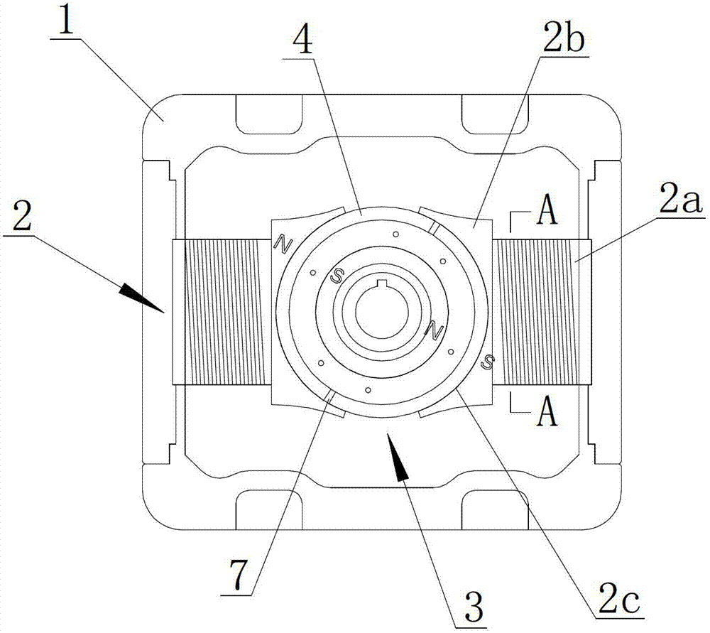
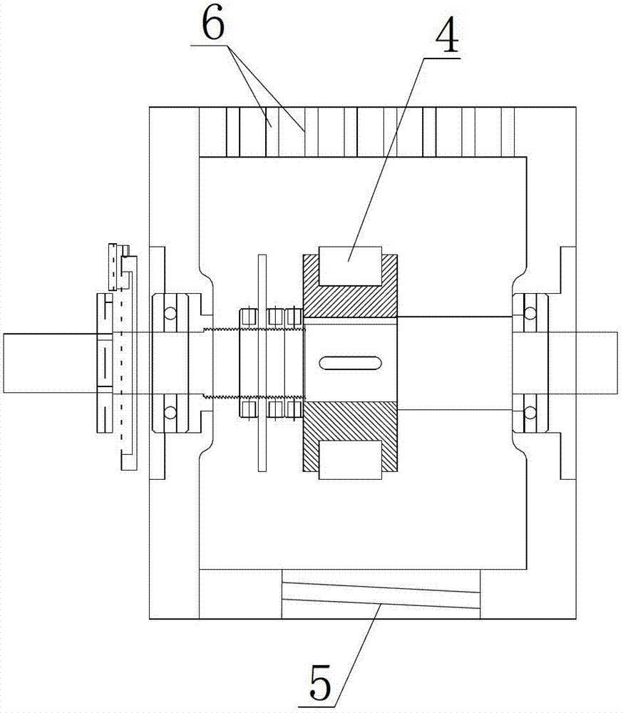
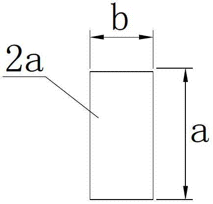
[0017] refer to Figure 1 to Figure 3 As shown, a low-speed high-torque permanent magnet brushless motor of the present invention includes a casing 1, and two stator electromagnets 2 corresponding to each other are provided along the circumference of the casing 1, and the stator electromagnet 2 is formed by a coil base 2a Composed of an extension seat 2b connected to the coil seat 2a, the end surface of the extension seat 2b away from the coil seat 2a is an arc-shaped surface 2c, and the arc of the arc-shaped surface 2c is 130-160°, preferably 140-145° , a winding space is formed in the casing 1 on both sides of the coil seat 2a, so that the fuselage part has a larger winding space under the same conditions; at the same time, the extension seats 2b on both sides of the arc surface 2c are triangular , so that the magnetic field intensity changes on both sides are different. This structure can improve the torque ripple and make the rotation more balanced; there is a rotor 3 on t...


PUM


Abstract

The invention discloses a low-speed large-torque permanent magnet brushless motor, and belongs to the technical field of a permanent magnet brushless motor. According to the main technical points, the low-speed large-torque permanent magnet brushless motor comprises a shell, wherein two mutual-corresponding stator electric magnets are arranged inside the shell along the circumference direction; each stator electric magnet consists of a coil base and an extending base connected with the coil base; the end face of each extending base, which is far from the coil base, is an arc face; the radian of each arc face is 130-160 degrees; a coiling space is formed inside the shell at the both sides of the coil base; a rotor is arranged on the shell between the two arc faces; two arc permanent magnets corresponding to the stator electric magnets are distributed on the rotor along the circumference direction; and the radian of each permanent magnet is 175-177.5 degrees. The invention aims to provide the low-speed large-torque permanent magnet brushless motor with a compact structure, larger internal space of a stator and low no-load consumption, and is used for providing power for other mechanical machines.

Description

technical field [0001] The invention relates to a motor, more specifically, to a low-speed and high-torque permanent magnet brushless motor. Background technique [0002] The common problems in ordinary motors are due to structural reasons, which make the equipment unable to perform well. The first is the stator structure. The grooves limit the number of winding turns of the copper wire, which makes it impossible to increase the strength of the magnetic field of the inductor and the current and voltage. At the same time, it cannot overcome the influence of temperature changes, resulting in high power loss and waste of resources. [0003] In addition, the structure of the rotor also has problems. In addition to naturally offsetting the magnetic flux leakage of the groove, the balance factors such as the centrifugal force of the rotor rotation, the accelerated wear of the left and right two-end bearings and the cutting of the magnetic force line caused by the impact make the r...

Claims


Application Information

Patent Timeline
Patent Type & Authority Patents(China)
IPC IPC(8): H02K29/03
Inventor 曾远维
Owner 深圳市科维特机电开发控制有限公司
Learn More