
Multifunctional digital fire fighting and rescue site charge terminal

A multi-functional, on-site technology, applied in the direction of signal transmission system, two-party line system stations, instruments, etc., can solve the problems of small coverage, difficulty in fully grasping the situation of the fire scene, and the inability of the commander to fully grasp the basic situation of the fire scene, etc., to achieve command Effect of effect improvement

Inactive Publication Date: 2013-06-26
NO 50 RES INST OF CHINA ELECTRONICS TECH GRP
View PDF2 Cites 1 Cited by
  • Summary
  • Abstract
  • Description
  • Claims
  • Application Information

AI Technical Summary

Problems solved by technology

[0003] (1) There are shortcomings in the means of communication
[0004] 350M wireless conventional voice communication has low power consumption, but the coverage area is small, and the data transmission function is insufficient. It is difficult to meet the use requirements when the fire is serious and the fire scene is complicated.
[0005] (2) The information transmission method is relatively single, and it is difficult to fully grasp the situation of the fire scene
[0006] At present, the firefighting force mainly transmits information through voice, and it is difficult to clearly express the basic conditions such as the temperature and pressure of the fire scene, the signs and equipment of the combatants, the location of the combatants, and the use of fire extinguishing agents and equipment through voice. There will be deviations due to various reasons, so that the commander cannot fully grasp the basic situation of the fire scene

Method used


Image

  • Multifunctional digital fire fighting and rescue site charge terminal

Examples


Embodiment Construction

[0031] The present invention will be further described below in conjunction with specific embodiment and accompanying drawing, set forth more details in the following description so as to fully understand the present invention, but the present invention can obviously be implemented in many other ways different from this description, Those skilled in the art can make similar promotions and deductions based on actual application situations without violating the connotation of the present invention, so the content of this specific embodiment should not limit the protection scope of the present invention.

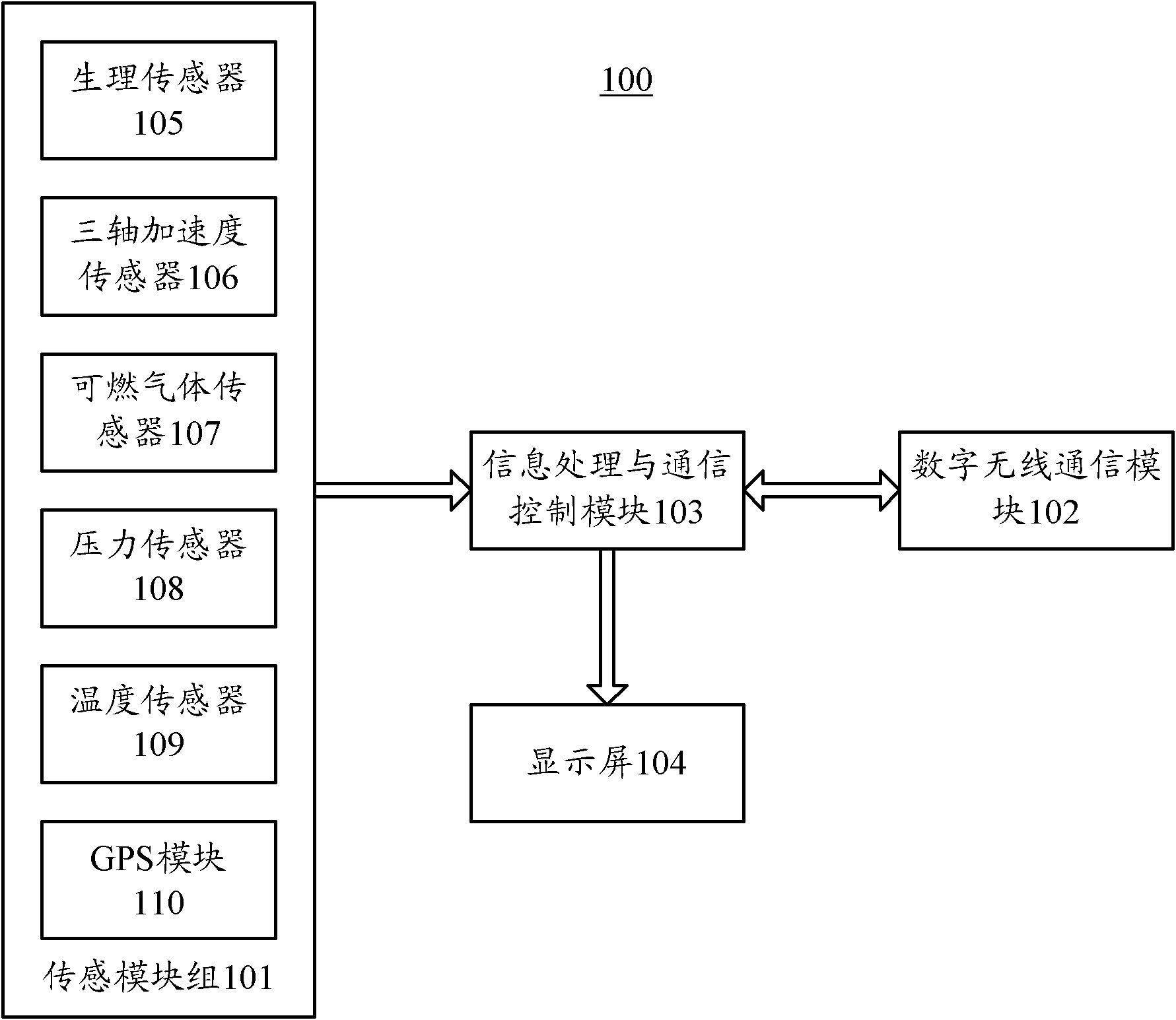
[0032] figure 1 It is a structural schematic diagram of a multifunctional digital fire fighting and rescue on-site command terminal according to an embodiment of the present invention. Such as figure 1 As shown, the multifunctional digital fire fighting and rescue on-site command terminal 100 may include: a sensing module group 101 , a digital wireless communication module 102...


PUM


Abstract

The invention provides a multifunctional digital fire fighting and rescue site charge terminal which comprises a sensing module group, a digital wireless communication module, an information processing and communication control module and a display screen. The sensing module group is used for acquiring environment information of a fire fighting and rescue site and physiological information of firefighters. The digital wireless communication module is used for achieving a voice communication / data transmission function of the system. The information processing and communication control module is respectively connected with the sensing module group and the digital wireless communication module and used for being responsible for the human-computer interface, controlling the modules to work in coordination and processing relative data. The display screen is connected with the information processing and communication control module and used for displaying a required result through graphs and numbers. The terminal adopts the digital technology, has the functions of voice communication, data transmission, physiological / environment information sensing, personnel location and the like, can be used for command work in the fire fighting and rescue site, plays a positive role in successful treatment of disaster accidents and protection of life safety of the firefighters, and changes the current situation of fire fighting and rescue work.

Description

technical field [0001] The invention relates to the technical field of on-site command and control systems for fire extinguishing and rescue, in particular, the invention relates to a multifunctional digital on-site command and control terminal for fire extinguishing and rescue. Background technique [0002] At present, the on-site command of fire fighting and rescue mainly adopts 350M conventional wireless communication equipment, which has played an active role in the actual combat of fire fighting and rescue. However, there are still some problems in the communication technology currently used, mainly including: [0003] (1) There are shortcomings in the means of communication [0004] 350M wireless conventional voice communication has low power consumption, but the coverage area is small, and the data transmission function is insufficient. It is difficult to meet the use requirements when the fire is serious and the fire scene is complicated. [0005] (2) The informatio...

Claims


Application Information

Patent Timeline
Patent Type & Authority Applications(China)
IPC IPC(8): H04Q5/24H04L29/08G08C17/02
Inventor 纪华
Owner NO 50 RES INST OF CHINA ELECTRONICS TECH GRP
Learn More