

Heating system and method for controlling heating system
A heating system and control method technology, applied in district heating systems, hot water central heating systems, heating systems, etc., can solve the problems of staying and not disclosing the thermal control of collective housing, and achieve the reduction of heat consumption and the improvement of comfort Effect
- Summary
- Abstract
- Description
- Claims
- Application Information
AI Technical Summary
Problems solved by technology
Method used
Image

Examples
Embodiment approach 1
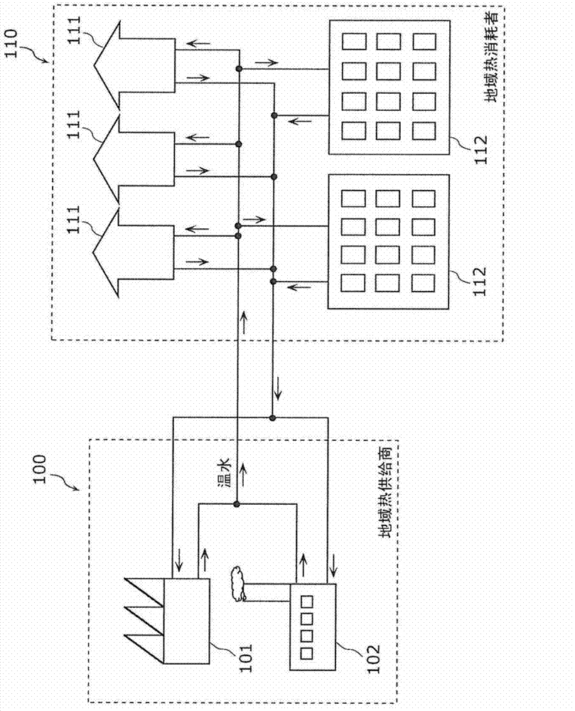
[0075] First, refer to Figure 7A with Figure 7B The structure of the heating system of Embodiment 1 is demonstrated. Figure 7A It is a figure which shows the example of the equipment in the collective house 112 required for heating each room with the warm water supplied from the district heat supplier 100. Figure 7B will be Figure 7A An enlarged view of one of the rooms shown.
[0076] Such as Figure 7A with Figure 7B As shown, a heat exchanger 210 , a heat meter 211 , a pump 212 , an outside air temperature sensor 213 , and a heating system control unit 214 are installed in a collective house 112 . In addition, each room of the collective house 112 has a radiator 201, a valve 202, a room temperature sensor 203, and a heating device control unit 204. In addition, in Figure 7A with Figure 7B In , the solid arrows represent the flow of warm water, and the dashed arrows represent the flow of information (signals).
[0077] The heat exchanger 210 is a device for ex...
Embodiment approach 2
[0119] Below, refer to Figure 13 It is a figure explaining the outline|summary of the control process of the heating system of Embodiment 2. Also, for Figure 8 The same processes are denoted by the same reference numerals, and explanations thereof are omitted. Figure 8 with Figure 13 The difference is the calculation method of the threshold temperature ( Figure 8 S220 and Figure 13 S221, S222), other processing is the same. Specifically, in Embodiment 2, the room temperature drop rate of each room is calculated from the outside air temperature ( S221 ), and the threshold temperature is determined for each room based on the room temperature drop rate ( S222 ). In addition, in Embodiment 2, steps S221 and S222 are executed by the heating system control unit 214 . However, the above-mentioned sharing of functions is just an example and is not limited thereto.
[0120] refer to Figure 14 with Figure 15 The threshold temperature determination process in Embodiment ...
Embodiment approach 3
[0129] Below, refer to Figure 16 It is a figure explaining the outline|summary of the control process of the heating system of Embodiment 3. Also, for Figure 8 The same processes are denoted by the same reference numerals, and explanations thereof are omitted. First, in Figure 16 In the control process, the heat dissipation of all heating devices is stopped from the SO start time to the SO end time, so there is no need to calculate the threshold temperature ( Figure 8 S220) and the process of comparing the room temperature with the threshold temperature ( Figure 8 S240). On the other hand, in Figure 16 A new process is added to the control process of acquiring the room temperature of each room at the end time of the SO period (S241), and determining the cooling resumption sequence of the heating device based on the acquired room temperature (S242). In addition, in Embodiment 3, step S241 is executed by the heating device control unit 204 , and step S242 is executed...
PUM
 Abstract
Description
Claims
Application Information