Pneumatic tire

A technology for pneumatic tires and tires, applied in tire parts, tire tread/tread pattern, transportation and packaging, etc., can solve the problems of easy reduction of lateral rigidity of the tread portion and reduced handling stability on dry road surfaces.

Active Publication Date: 2013-07-03
SUMITOMO RUBBER IND LTD
View PDF6 Cites 17 Cited by
  • Summary
  • Abstract
  • Description
  • Claims
  • Application Information

AI Technical Summary

Problems solved by technology

[0005] However, if only the above-mentioned longitudinal grooves, lateral grooves, and sipes are provided on the tread portion, the lateral rigidity of the tread portion tends to decrease, thereby reducing the handling stability on dry roads.

Method used


Image

  • Pneumatic tire
  • Pneumatic tire
  • Pneumatic tire

Examples


Embodiment

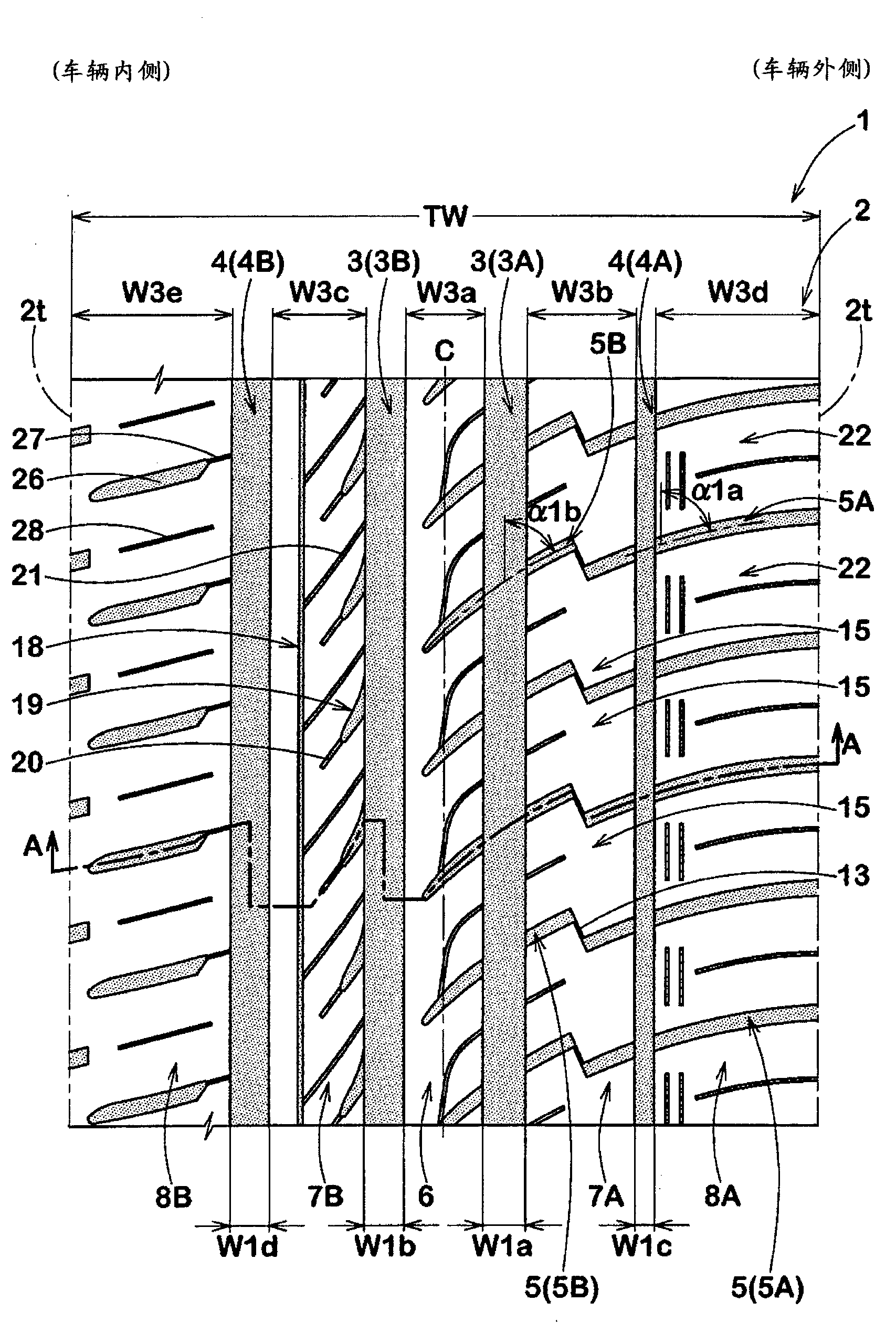
[0087] Made to form figure 1 The tires with the basic structure shown in Table 1 and with the longitudinal grooves, transverse grooves and sipes shown in Table 1, and their performances were evaluated.

[0088] In addition, the same evaluation was performed on the following tires as a comparison, namely: Figure 5 A tire shown in (a) in which the inner shoulder land portion is divided into blocks and does not have an inner shoulder auxiliary groove (comparative example 1), Figure 5 A tire in which the outer shoulder land portion shown in (b) is formed of straight ribs (Comparative Example 2), and Figure 5 The tire shown in (c) without the inner middle sub groove and the inner middle sipe (comparative example 3). In addition, common specifications are as follows.

[0089] Tread contact width TW: 194mm

[0090] Lateral central longitudinal groove:

[0091] Groove width W1a: 11.4mm, maximum groove depth D1a: 9.5mm

[0092] Medial central longitudinal groove:

[0093] Gro...


PUM


Abstract

The present invention provides a pneumatic tire capable of improving the drainage performance, on-snow performance, and on-ice performance while maintaining the steering stability on a dry road surface. The pneumatic tire (1) has a designated mounting orientation with respect to a vehicle. A tread portion (2) divided into a center land portion (6), an outer middle land portion (7A), an inner middle land portion (7B), an outer shoulder land portion (8A), and an inner shoulder land portion (8B); the outer shoulder land portion (8A) enables outer shoulder blocks (22) which are sectioned by outer shoulder lateral grooves (5A) to be arranged circumferentially on the tire in a space manner; the inner shoulder land portion includes inner shoulder lateral grooves (26) having outer ends which are on the outside of the vehicle and form terminals in the land portion (8B), and inner shoulder auxiliary grooves (28); the inner middle land portion includes an inner middle sub-groove (18) which continuously extends in a circumferential direction and inner middle sipes (21) which extend between the inner middle sub-groove and the inner center longitudinal groove (3B).

Description

technical field [0001] The present invention relates to a pneumatic tire capable of maintaining handling stability on dry roads and improving water drainage performance, performance on snow, and performance on ice. Background technique [0002] Pneumatic tires (also referred to as all-season tires) are known that improve not only the running performance on dry roads but also the running performance on icy and snowy roads and the like. Such a tire is provided with a plurality of blocks divided by longitudinal grooves extending in the tire circumferential direction and lateral grooves extending in the tire axial direction in a tread portion. Such longitudinal grooves and transverse grooves can smoothly drain the water film sandwiched between road surfaces, and can sink into snowy roads to obtain snow column shearing force, thereby improving drainage performance and on-snow performance. [0003] In addition, for example, a sipe extending in the tire axial direction is provided...

Claims


Application Information

Patent Timeline
Patent Type & Authority Applications(China)
IPC IPC(8): B60C11/03B60C11/117
CPCB60C11/0306B60C11/1369B60C11/0304B60C2011/0388B60C2011/0353B60C2011/0369B60C2011/0348B60C2011/1254B60C11/12B60C2011/0381B60C2011/0393B60C11/01B60C11/11B60C11/03B60C11/04B60C11/13B60C2011/039B60C2011/0341B60C2011/0386B60C2011/036B60C11/032
Inventor 羽田圭宽
Owner SUMITOMO RUBBER IND LTD
Why Eureka
Try Eureka