Extra-high-pressure wall bushing

A through-wall bushing, UHV technology, applied in electrical components, substation/switch layout details, etc.

Inactive Publication Date: 2013-07-03
山东彼岸电力科技有限公司
View PDF6 Cites 8 Cited by
  • Summary
  • Abstract
  • Description
  • Claims
  • Application Information

AI Technical Summary

Problems solved by technology

The main manifestations are: the insulation performance is reduced under polluted conditions, the voltage of wet flashover and pollution flashover is low; the mechanical strength is difficult to meet the operation requirements, and it is easy to break; the production process is complex and the yield is extremely low
At present, the UHV bushings designed and manufactured by electrical equipment enterprises at home and abroad are all oil-immersed AC UHV bushings, and the main insulation adopts oil-immersed multi-screen wrapping technology scheme, which has complicated process and high requirements for production process control. There are shortcomings such as large partial discharge and large dielectric loss, and the main insulation is prone to defects such as aging; the insulation medium uses transformer oil, which makes it weigh more than 15 tons, which is very heavy; and the development of transmission and distribution stations at home and abroad currently requires equipment Oil-free trend
[0005] At present, the UHV wall bushings used in power plants and substations at home and abroad are oil-insulated porcelain bushings. Due to the high voltage level, high electrical and mechanical performance requirements , the production process is complicated, especially the ultra-large composite wall-piercing bushing with high reliability and high safety for ±1100kV UHV equipment has not been successfully developed

Method used


Image

  • Extra-high-pressure wall bushing
  • Extra-high-pressure wall bushing
  • Extra-high-pressure wall bushing

Examples


Embodiment Construction

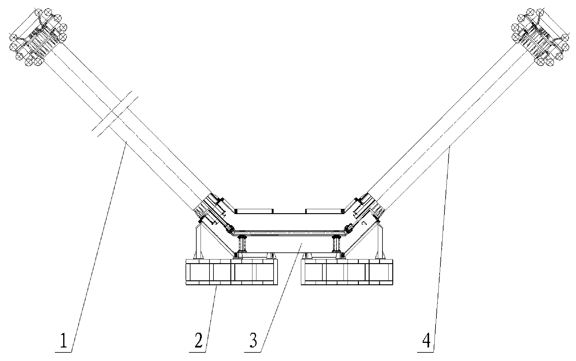
[0023] like figure 1 The UHV wall-piercing bushing shown in the figure includes an outdoor bushing 1, an intermediate connecting pipe 3 and an indoor bushing 4 connected in sequence. The outdoor bushing 1 and the indoor bushing 4 are straight pipes, and the outdoor bushing 1 The lower end of the lower end of the casing 4 and the lower end of the indoor casing 4 are respectively connected to the two ends of the intermediate connecting pipe 3, and the outdoor casing 1 and the indoor casing 4 are respectively inclined towards the two outer sides of the intermediate connecting pipe 3, so that the overall shape forms a V-like shape. font, the intermediate connecting pipe 3 is connected with a ground support.

[0024] The middle straight ends of the intermediate connecting pipe 3 are tilted upwards, and the angles between the two ends of the intermediate connecting pipe 3 and the middle part are 120-150 degrees. Part of the angle is 120-150 degrees.

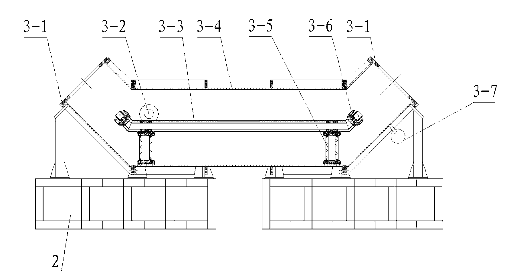
[0025] like figure 2 As sh...


PUM


Abstract

The invention discloses an extra-high-pressure wall bushing. The extra-high-pressure wall bushing disclosed by the invention comprises an outdoor bushing, a middle connecting pipe and an indoor bushing which are sequentially connected, wherein the outdoor bushing and the indoor bushing are straight pipes, the lower end of the outdoor bushing and the lower end of the indoor bushing are respectively connected with the two ends of the middle connecting pipe, the outdoor bushing and the indoor bushing respectively incline towards the two outer sides of the middle connecting pipe, and the middle connecting pipe is connected with a ground support. According to the extra-high-pressure wall bushing, because the overall bushing is similar like a V shape, the part of the wall bushing, which is connected with a wall body, does not need to be arranged at a higher position of the wall body and can be supported by the arranged ground support, thereby reducing the pressure on the wall body and lowering the requirement on the mechanical strength of the wall body; after the wall bushing is installed, the outdoor bushing and the indoor bushing extend from the lower position of the wall body to a high position far away from the wall body, so that more low-position space is not occupied, thereby facilitating the arrangement of other things; and the situations that traditional extra-high-pressure wall bushings are inconvenient to transport and lift and parts of traditional extra-high-pressure wall bushings are difficultly processed are completely changed.

Description

Technical field [0001] The present invention involves a high -voltage electrical component, which specializes in a high -voltage wall tube. Background technique [0002] UHV abbreviation UHV, this patent high voltage in this patent refers to the voltage level of 500 kV and DC ± 500 kV. [0003] Traditional wall -piercing tube is mainly "one" -shaped design, because of the requirements of insulation performance, it must be installed on the wall of the building.This puts forward high mechanical strength requirements for the requirements of the building, and even considers the requirements of electrical strength. [0004] The traditional wall -piercing tube is mainly made of a capacitor core in the insulation roll of oil -soaking paper into the transformer oil.The components made of ceramics or glass are both mechanical load and electrical load. As the voltage level increases, the mechanical load of the sleeve is increased, and the current conditions of air pollution.Out of its inhe...

Claims


Application Information

Patent Timeline
Patent Type & Authority Applications(China)
IPC IPC(8): H02B1/00H02G3/22
Inventor 刘应平
Owner 山东彼岸电力科技有限公司
Why Eureka
Try Eureka