Method and device for eliminating harmonic wave of photovoltaic grid connected charging system
A charging system and photovoltaic battery technology, applied to harmonic reduction devices, AC networks to reduce harmonics/ripples, etc., can solve problems such as high cost of APF, performance impact of three-phase AC power grid, and single function
- Summary
- Abstract
- Description
- Claims
- Application Information
AI Technical Summary
Problems solved by technology
Method used
Image
Examples
Embodiment 1
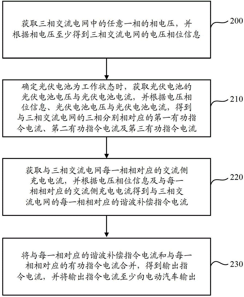
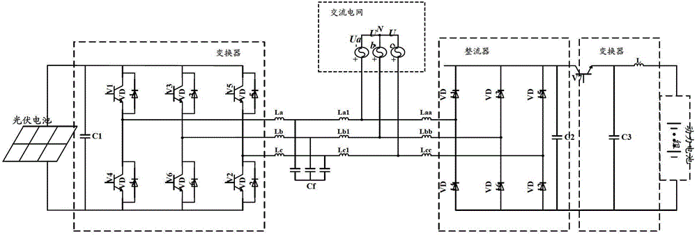
[0036] The detailed process of calculating the first active command current, the second active command current and the third active command current corresponding to the three phases (A-phase, B-phase and C-phase), respectively, will be illustrated below (wherein the three-phase AC The grid is G, the photovoltaic cell is H):
[0037] Step a1: Obtain the phase voltage of the A phase of G, and obtain the voltage phase information θ according to the phase voltage;
[0038] Step b1: When it is determined that H is in the working state, obtain the voltage U of H H with current I H ;
[0039] Step c1: According to U H with I H Use MPPT method to obtain U corresponding to the maximum power value of H / H ;
[0040] Step d1: According to U H with U / H Calculate the error voltage ΔU H , and according to ΔU H Calculate the first active command current I corresponding to phase A A ;
[0041] Step e1: According to I A And use the corresponding relationship rule to calculate...
Embodiment 2
[0045] The detailed process of calculating the harmonic compensation command currents corresponding to the three phases (A-phase, B-phase, and C-phase) of the three-phase AC power grid is illustrated below (wherein the three-phase AC power grid is G, and the photovoltaic cell is h):
[0046] Step a2: Obtain the phase voltage of the A phase of G, and obtain the voltage phase information θ according to the phase voltage;
[0047] Step b2: Obtain the AC side charging current I corresponding to each of the three phases respectively A0 , I B0 with I C0 ;
[0048] Step c2: put I A0 , I B0 with I C0 Transform to get I α with I β ;
[0049] In this step, after obtaining I α with I β During the process, I can A0 , I B0 with I C0 Through the abc / αβ converter, the transformation from the three-phase stationary coordinate system to the two-phase stationary coordinate system is realized, and I get α with I β .
[0050] Step d2: put I again α with I β Transform to obtain ...
Embodiment 3
[0062] The detailed process of calculating the output command current obtained by combining the harmonic compensation command current corresponding to each phase and the active command current corresponding to each phase is illustrated below (wherein the three-phase AC grid is G, photovoltaic battery is H):
[0063] Step a3: the I obtained by step d1 and step e1 in the embodiment one A , I B with I C Transform to get the d-axis given current I d_pv , q-axis given current I q_pv , and let I q_pv =0;
[0064] In this embodiment, through the voltage regulator, after the proportional and integral operations of the voltage regulator, I A , I B with I C , get I d_pv with I q_pv .
[0065] Step b3: the I obtained in the step i2 in the embodiment two a_href , I b_href with I c_href Transform to get I d_href with I q_href ;
[0066] Step c3: put I d_pv with I d_href Combined to obtain the d-axis output command current I d_out ; put I q_pv with I q_href Combined to...
PUM
 Abstract
Description
Claims
Application Information
 - R&D
- Intellectual Property
- Life Sciences
- Materials
- Tech Scout
- Unparalleled Data Quality
- Higher Quality Content
- 60% Fewer Hallucinations
Browse by: Latest US Patents, China's latest patents, Technical Efficacy Thesaurus, Application Domain, Technology Topic, Popular Technical Reports.
© 2025 PatSnap. All rights reserved.Legal|Privacy policy|Modern Slavery Act Transparency Statement|Sitemap|About US| Contact US: help@patsnap.com


