Modular converter circuit having sub-modules, which are operated in linear operation

A converter and sub-module technology, applied in the direction of output power conversion device, AC power input conversion to DC power output, electrical components, etc., can solve the problem of low power, achieve simple manufacturing and operation, small loss, avoid The effect of harmonics

Active Publication Date: 2016-11-16
SIEMENS AG
View PDF5 Cites 1 Cited by
  • Summary
  • Abstract
  • Description
  • Claims
  • Application Information

AI Technical Summary

Problems solved by technology

Due to the high cooling requirements, only applications with relatively low power can be reasonably realized

Method used


Image

  • Modular converter circuit having sub-modules, which are operated in linear operation
  • Modular converter circuit having sub-modules, which are operated in linear operation
  • Modular converter circuit having sub-modules, which are operated in linear operation

Examples


Embodiment Construction

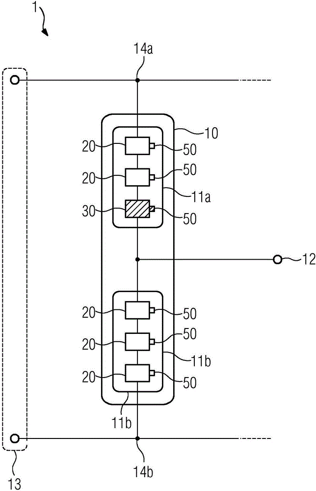
[0039] figure 1 An embodiment of an inverter circuit 1 according to the invention is shown. It has a DC voltage connection 13 . Thereby, the phase module 10 is connected to its interfaces 14a, 14b. The phase module 10 comprises a series circuit of an upper converter valve 11a and a lower converter valve 11b. The connection point of the two converter valves 11a and 11b forms the connection 12 on the AC voltage side. The two converter valves 11a and 11b in turn have a series circuit of one submodule 20 , 30 each. Each such submodule is connected to a drive assembly, which is advantageously arranged near the submodules 20 , 30 or even inside the submodules 20 , 30 . In the embodiment shown, the upper converter valve has a sub-module 30 suitable for linear operation. It is actuated via its actuating assembly 50 in such a way that a voltage with a continuous time profile can be generated at the output on the alternating voltage side with respect to the reference potential. An...


PUM


Abstract

The invention relates to a converter circuit (1), comprising a direct-voltage connection (13); at least one alternating-voltage connection (12); and at least one phase module (10), wherein the phase module (10) has a series connection of an upper and a lower converter valve (11a, 11b), wherein an electrical link between the upper and the lower converter valve (11a, 11b) is the alternating-voltage connection (12), wherein the connections (14a, 14b) of the phase module (10) are electrically connected to the direct-voltage connection (13), wherein the upper and the lower converter valve (11a, 11b) each have at least two sub-modules (20, 30), which are arranged electrically in series, wherein the sub-modules (20, 30) have at least one capacitor (42), at least one power semiconductor (41), and a control assembly (50) for controlling the power semiconductors (41), wherein at least one converter valve (11a, 11b) has a sub-module (30) suitable for linear operation, and wherein the converter circuit (1) has a control assembly (50), which enables the linear operation of the sub-module (30) suitable for linear operation. The invention further relates to a method for operating a converter circuit (1) according to the invention, wherein at least one sub-module (30) is operated in linear operation in at least one converter valve (11a, 11b).

Description

technical field [0001] The invention discloses a converter circuit, which has: [0002] - DC voltage interface; [0003] - at least one interface on the AC voltage side; and [0004] - at least one phase module, [0005] wherein the phase module has a series circuit of an upper converter valve and a lower converter valve, [0006] Among them, the electrical connection between the upper converter valve and the lower converter valve is represented as an interface on the AC voltage side, [0007] Wherein, the interface of the phase module is electrically connected with the DC voltage interface, [0008] Wherein, the upper converter valve and the lower converter valve respectively have at least two sub-modules arranged electrically in series, [0009] In this case, the submodule has at least one capacitor and at least one power semiconductor. Background technique [0010] Inverters are applied to convert electrical power in terms of voltage level, current level, frequency ...

Claims


Application Information

Patent Timeline
Patent Type & Authority Applications(China)
IPC IPC(8): H02M1/12H02M7/483
CPCH02M1/12H02M7/483H02M7/4835H02M7/537
Inventor 克里斯蒂安·弗里德里希
Owner SIEMENS AG
Why Eureka
Try Eureka