X-ray generating mechanism using electron field emission cathode

A field emission cathode and ray generation technology, applied in the direction of X-ray tube with huge current, X-ray tube, cathode ray convergence/focusing/guidance, etc., can solve the problem of X-ray beam non-uniformity, low current density, etc. problems, achieve high beam current, high control and focus, improved image quality and speed

Inactive Publication Date: 2007-07-04
THE UNIV OF NORTH CAROLINA AT CHAPEL HILL
View PDF14 Cites 7 Cited by
  • Summary
  • Abstract
  • Description
  • Claims
  • Application Information

AI Technical Summary

Problems solved by technology

[0019] The use of diamond material as a field emitter also poses the problem that diamond produces a lower current density than is required
Therefore, even if the focal point is bombarded with a uniform electron beam, the resulting X-ray beam is still non-uniform

Method used


Image

  • X-ray generating mechanism using electron field emission cathode
  • X-ray generating mechanism using electron field emission cathode
  • X-ray generating mechanism using electron field emission cathode

Examples


Embodiment Construction

[0055] Detailed description of the preferred embodiment

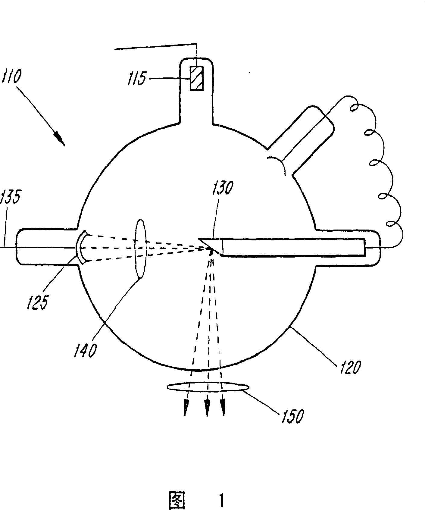
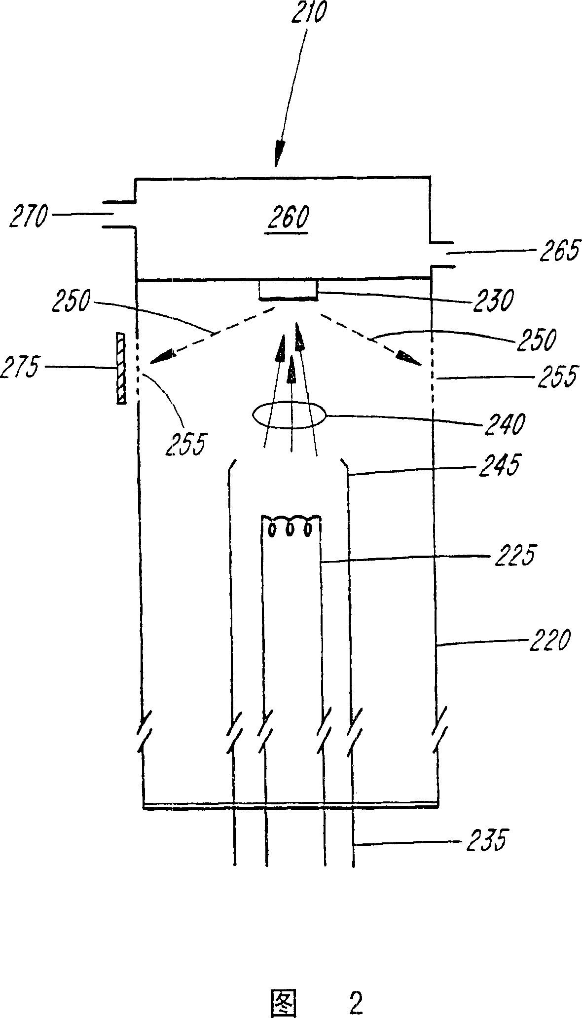
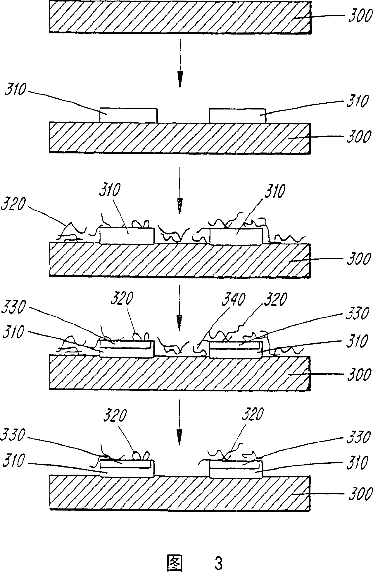
[0056] According to the invention, the cathode of the X-ray emitting device is formed at least partly by a material comprising nanostructures. Nanostructured materials have nanoscale dimensions. These nanostructures can have various shapes such as spheres, rods / wires or tubes.

[0057] The present invention contemplates the use of a variety of nanostructured materials with high emission current densities. For example, materials comprising silicon (Si), germanium (ge), aluminum (Al), silicon oxide, germanium oxide, silicon carbide, boron, boron nitride, and boron carbide are contemplated. The above materials are described in more detail, for example, in US Patent No. ____; (Serial No. 09 / 594,844, Attorney's Docket No. 032566-003), which is incorporated herein by reference in its entirety.

[0058] According to a further embodiment of the present invention, the material used to form at least a part of the cathode in th...


PUM


Abstract

An x-ray generating device includes a field emission cathode formed at least partially from a nanostructure (1110) containing material having an emitted electron current density of at least 4 A / cm2. High energy conversion efficiency and compact design (1100) are achieved due to easy focusing of cold cathode emitted electron between the cathode (1110) and the gate or anode (1130) and focusing the electron beams at different anode materials (1130), pulsed x-ray radiation with varying energy can be generated from a single device.

Description

[0001] Statement Regarding Federally Sponsored Research or Development Programs [0002] At least some aspects of this invention were made with Government support under a grant from the Office of Naval Research under Contract No. N00014-98-1-0597. The government has certain rights in this invention. Background of the invention [0003] In the following description, reference is made to certain structures and / or methods. However, citations below should not be taken as an admission that these structures and / or methods constitute prior art. Applicant expressly reserves the right to demonstrate that such structures and / or methods are not prior art with respect to the present invention. [0004] X-rays at about 10 -8 and 10 -12 The part of the electromagnetic spectrum between m. When bombarded by energetic electrons, atoms emit X-rays through two distinct processes. [0005] In the first process, high-speed electrons slow down as they pass through matter. If an individual el...

Claims


Application Information

Patent Timeline
Patent Type & Authority Applications(China)
IPC IPC(8): H01J35/06H01J35/08H01J35/04H01J35/22H01J35/00H05G1/00G21K5/02A61B6/00A61B6/03G21K5/08H05G1/34
CPCB82Y10/00H01J2201/30469A61B6/405A61B6/4488H01J2235/068H01J35/065H01J2235/064H01J35/22H01J35/14A61B6/4021A61B6/482Y10S977/939A61B6/032H05G1/34A61B6/4028H01J35/153
Inventor 周子刚卢健平
Owner THE UNIV OF NORTH CAROLINA AT CHAPEL HILL
Why Eureka
Try Eureka