Fan cooling control device and working method thereof

A control device and fan cooling technology, applied in engine control, pump control, circuit devices, etc., can solve the problems of fan cooling control device failure, affecting the operation of the air cooling system, low working reliability, etc., to correct the power factor of the grid , Guarantee the effect of stability and prolong life

Active Publication Date: 2016-01-13
CHANGZHOU POWER SUPPLY OF JIANGSU ELECTRIC POWER +2
View PDF8 Cites 1 Cited by
  • Summary
  • Abstract
  • Description
  • Claims
  • Application Information

AI Technical Summary

Problems solved by technology

[0002] In the prior art, transformers with a voltage level of 110kV and below often use a cooling fan to cool the transformer, and the working condition of the cooling fan directly affects the load capacity of the transformer; and the fan cooling control device often fails, according to statistics , the failure of the fan cooling control device is mainly divided into control circuit and component failure, and the main reason for the control circuit failure is that the control component uses an electromagnetic relay. The ability is poor, causing these components to be often burned and damaged, which affects the operation of the air cooling system, so how to design a replacement electromagnetic relay to control the entire fan cooling control device is a technical problem in this field

Method used


Image

  • Fan cooling control device and working method thereof
  • Fan cooling control device and working method thereof
  • Fan cooling control device and working method thereof

Examples


Embodiment l

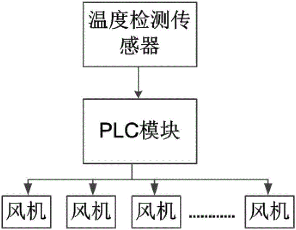
[0033] Such as figure 1 As shown, a fan cooling control device includes: a temperature detection sensor, a number of fans, and a PLC module connected to the temperature detection sensor and suitable for controlling the operation of a corresponding number of fans and the corresponding speed of the fans according to the external temperature. In the summer when the temperature of the fan is high, the heat generated by the transformer is huge, so when the temperature detected by the sensor reaches 60 degrees Celsius, all the fans are working, and the fan speed can be increased according to the ambient temperature; in winter with a low temperature, due to the ambient temperature Low, so when the calorific value of the transformer is not high, the fan can be turned on less or not, and the rotation speed of the fan can be appropriately reduced.

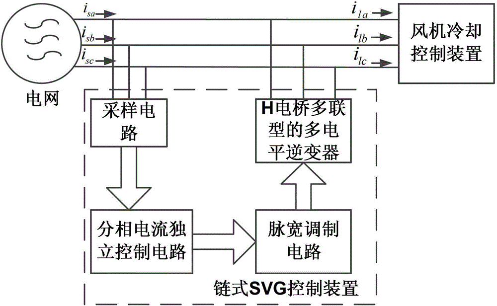
[0034] Such as figure 2 As shown, the fan cooling control device further includes: a chained SVG control device suitable for power factor...

Embodiment 2

[0071] See Figure 2-4 , on the basis of embodiment 1, the working method of the air-cooled control device includes:

[0072] The working method of the chained SVG control device provided at the three-phase power supply of the control device comprises the following steps:

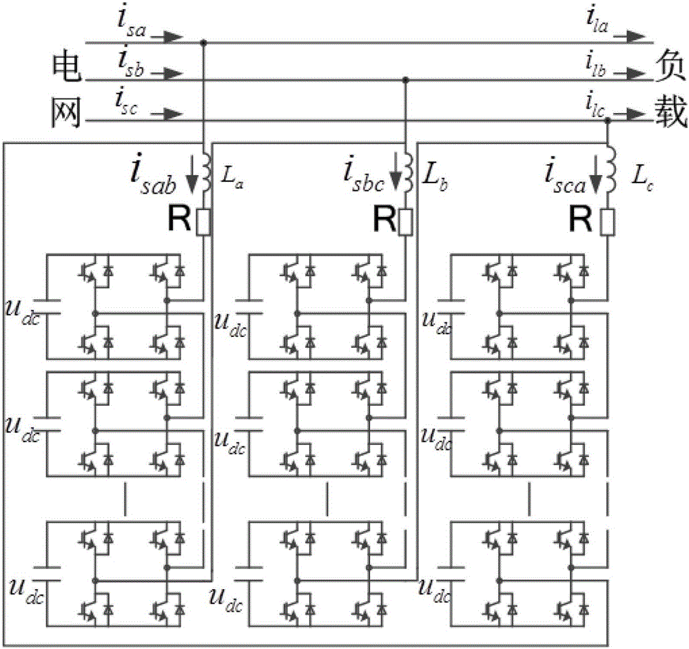
[0073] A: When an H bridge unit circuit is damaged, the corresponding automatic bypass circuit bypasses the H bridge unit circuit;

[0074] B: On the basis of keeping the sampling period of the sampling circuit unchanged, the pulse width modulation circuit changes the carrier triangular wave phase-shifting SPWM of the one-phase H-bridge power module where the damaged H-bridge unit circuit is located Carrier frequency, to obtain the pulse modulation waveform of the carrier triangular wave phase-shifting SPWM corresponding to the remaining H bridge unit circuit quantity in the phase H bridge power module;

[0075] The working method of the phase-splitting current independent control circuit comprises the fo...


PUM


Abstract

The invention relates to a fan cooling control device which comprises a temperature detection sensor, a plurality of fans and a PLC (Programmable Logic Controller) module which is connected with the temperature detection sensor and is suitable for controlling working of the fans with the corresponding number and corresponding rotational speeds of the fans according to the external temperature. According to the fan cooling control device disclosed by the invention, the traditional relay circuit is replaced by the PLC module, so that the defects of tedious wiring and high failure rate of relays are avoided; and the fan number and the rotation number are controlled according to the temperature, the fans do not need to started or a few fans are started with low revolution in winter with lower temperature, while all the fans need to be started in summer with high temperature, and the revolution is increased according to the specific temperature, so that a great deal of power is saved, and the service life of a motor is also prolonged.

Description

technical field [0001] The invention relates to a fan cooling control device and a working method thereof. Background technique [0002] In the prior art, transformers with a voltage level of 110kV and below often use a cooling fan to cool the transformer, and the working condition of the cooling fan directly affects the load capacity of the transformer; and the fan cooling control device often fails, according to statistics , the failure of the fan cooling control device is mainly divided into control loop and component failure, and the main reason for the control loop failure is that the control component uses an electromagnetic relay. Poor capacity causes these components to be often burned and damaged, which affects the operation of the air-cooled system. Therefore, how to design a replacement electromagnetic relay to control the entire fan cooling control device is a technical problem in this field. Contents of the invention [0003] The technical problem to be solve...

Claims


Application Information

Patent Timeline
Patent Type & Authority Patents(China)
IPC IPC(8): F04D27/00
CPCF04D27/004F04D27/007F04D27/008F05D2270/02F05D2270/303H01F27/085H02J3/01H02J3/1857H02J3/1892H02J3/26Y02B70/30Y02E40/10Y02E40/30Y02E40/40Y02E40/50Y04S20/20
Inventor 王庆刘江郭玉明许霖
Owner CHANGZHOU POWER SUPPLY OF JIANGSU ELECTRIC POWER
Why Eureka
Try Eureka