Radiating element for irradiating surfaces, having a socket

A radiator and irradiation technology, applied in the field of radiators, can solve the problems of inability to install and equipment consumption, etc.

Inactive Publication Date: 2013-07-03
OSRAM GMBH
View PDF7 Cites 1 Cited by
  • Summary
  • Abstract
  • Description
  • Claims
  • Application Information

AI Technical Summary

Problems solved by technology

Disadvantages are the additional outlay for equipment and the need for coordination between flushing device and radiator
Furthermore, the systems generally cannot be fitted into cavities such as cans or bottles with narrow openings for reasons of space

Method used


Image

  • Radiating element for irradiating surfaces, having a socket
  • Radiating element for irradiating surfaces, having a socket
  • Radiating element for irradiating surfaces, having a socket

Examples


Embodiment Construction

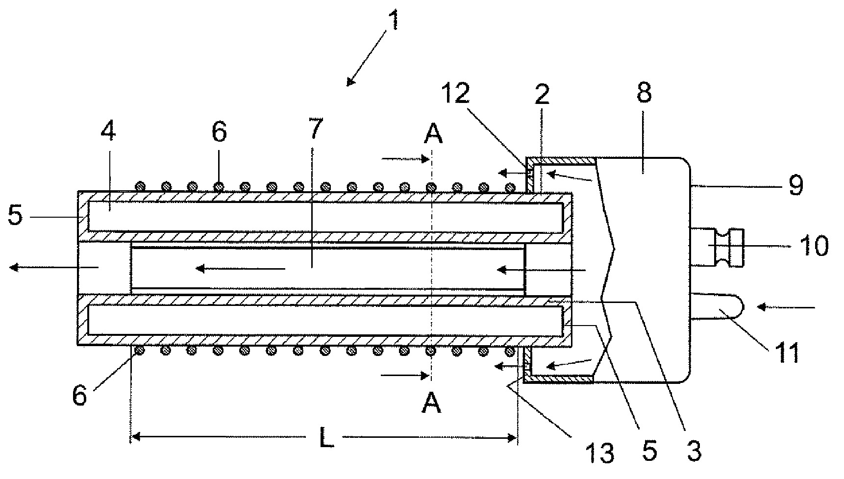
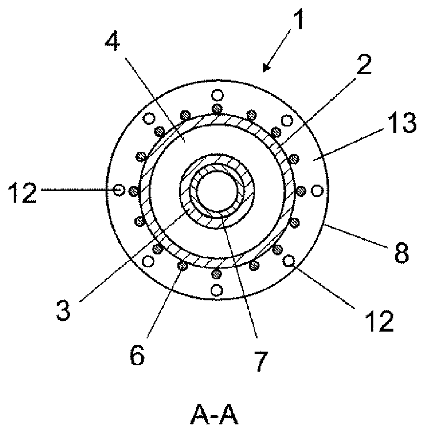
[0026] Figure 1a , 1bA partially broken longitudinal view and a cross-sectional view of a first exemplary embodiment of a radiator 1 according to the invention based on a dielectric barrier discharge are shown in a very schematic illustration. The elongated discharge vessel of the radiator 1 consists of an outer tube 2 and an inner tube 3 in a coaxial twin-tube construction, which thus define the longitudinal axis of the discharge vessel. The length of the tube varies according to the application. In order to sterilize the bottle, for example, the length is advantageously determined such that the inside of the bottle is completely irradiated when the radiator sinks in. The diameter of the tube is likewise advantageously adapted to the application. In particular, the largest outer diameter of the discharge vessel is dimensioned such that the radiator 1 can be inserted, for example, into a container provided for irradiation, for example into a bottle through the neck of the b...


PUM


Abstract

The invention relates to a radiating element (1) for irradiating surfaces, having a socket (8), wherein the socket has at least one gas opening (12) for supplying a process gas into a spatial region adjacent to the vessel (2, 3, 5) of the radiating element. A separate gas supply device can thereby be omitted. The vessel (2, 3, 5) of the radiating element can optionally also have a tunnel-like passage (3) for supplying or discharging process gas.

Description

technical field [0001] The invention relates to a radiator with a base for irradiating surfaces with electromagnetic radiation. In particular, the invention relates to a radiator emitting short-wave ultraviolet (UV) radiation, preferably below 200 nm. Furthermore, such radiators can be used for disinfecting surfaces, for example flat foils and the interior of bottles, jars or other hollow containers. Background technique [0002] When UV irradiating surfaces, in particular disinfecting them, it can be advantageous to irradiate the space between the radiator and the surface with flushing gas, at least during the irradiation and, if necessary, before and / or after the irradiation. rinse. Thereby, at least during irradiation, UV radiation-absorbing gases should be removed between the surface to be irradiated and the UV radiator. In particular nitrogen or noble gases are suitable as flushing gas. Also in other irradiation processes, a defined atmosphere between the radiator a...

Claims


Application Information

Patent Timeline
Patent Type & Authority Applications(China)
IPC IPC(8): H01J65/04H01J5/48H01J61/30
CPCA61L2/10A61L2202/23H01J5/48H01J5/56H01J61/305H01J65/046
Inventor 赫尔穆特·哈尔夫曼阿克塞尔·洪巴赫马库斯·罗特
Owner OSRAM GMBH
Why Eureka
Try Eureka