Self-locking bracket

A self-locking, bracket technology, applied in the field of orthodontics, can solve the problems of difficult manufacturing, difficult operation, high price, etc., and achieve the effects of simple production, no cumbersome operation, and convenient operation.

Inactive Publication Date: 2013-07-10
王光良
View PDF3 Cites 8 Cited by
  • Summary
  • Abstract
  • Description
  • Claims
  • Application Information

AI Technical Summary

Problems solved by technology

At present, there are many kinds of self-locking brackets on the market, including two series of active type and passive type, but the structure is relatively complicated, the manufacture is difficult, the cost is high, the price is expensive, and the operation is difficult.

Method used


Image

  • Self-locking bracket
  • Self-locking bracket
  • Self-locking bracket

Examples


Embodiment

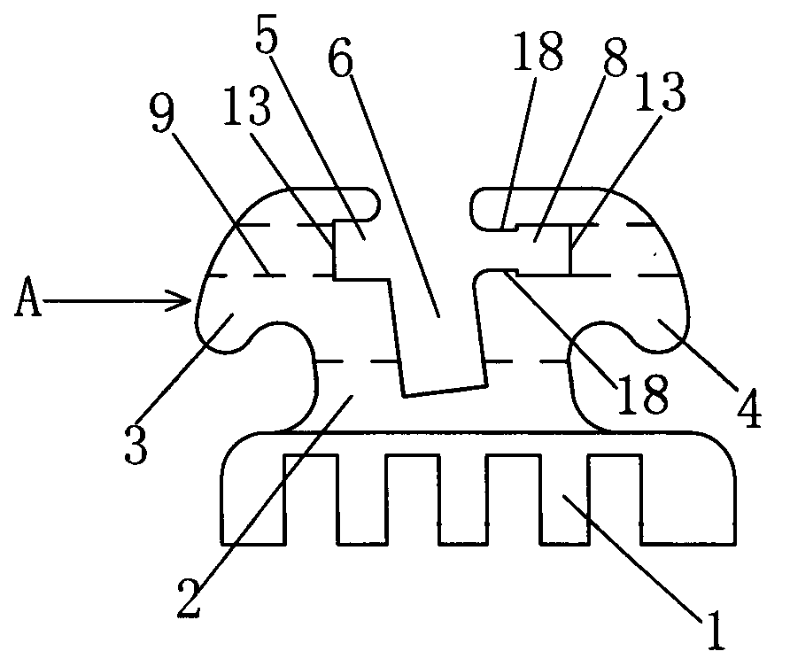
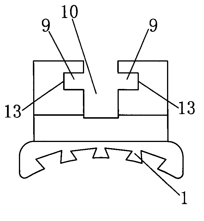
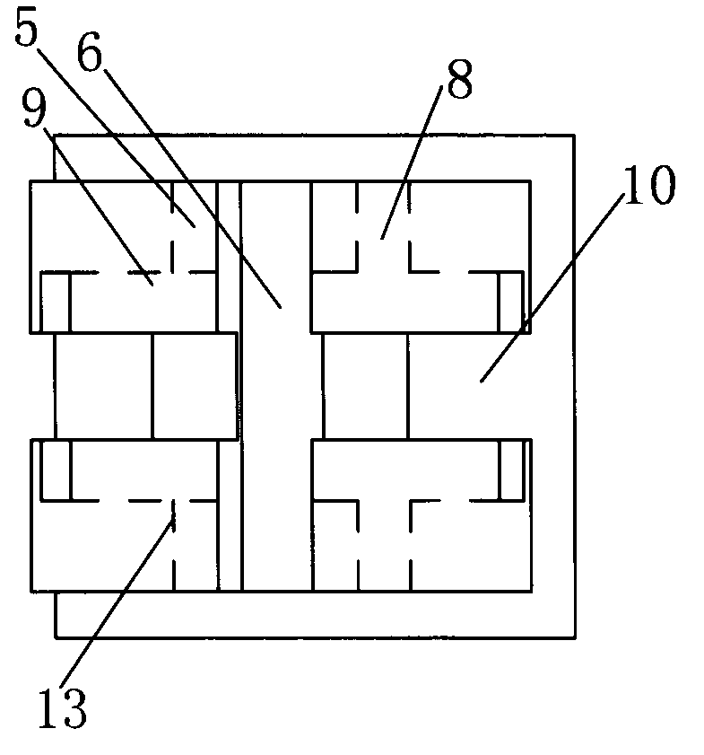
[0022] Embodiment: a kind of self-locking bracket, as Figure 1~3 As shown, it includes a bracket body 2 with a mesh bottom 1 and an archwire groove 6. The two sides of the archwire groove 6 are provided with working wings 3 and 4, and the bracket body 2 intersects the archwire groove 6 with The bracket opening 10, the bracket opening 10 and the archwire groove 6 are intersected, and the bracket opening 10 and the archwire groove 6 divide the working wings 3 and 4 into four separate pieces, as figure 1 , figure 2 As shown, the two sides of the bracket opening 10 are symmetrically provided with the chute 9 formed by wire cutting, and the chute 9 is vertically provided with a groove edge 13 .

[0023] like Image 6 , Figure 7 As shown, a bracket cover 11 is slid in the chute 9, as Figure 4 , Figure 5 As shown, the two sides of the bracket cover 11 are provided with slide bars 15 that cooperate with the chute 9, a gap 50 is provided between the two slide bars 15 at the f...


PUM


Abstract

The invention discloses a self-locking bracket comprising bracket body having an archwire groove and a bracket opening, wherein two sides of the bracket opening are symmetrically provided with sliding grooves, insides of the sliding grooves are provided with vertical groove edges, a bracket cover is slidedly arranged in the sliding grooves, two sides of the bracket cover are provided with sliding strips cooperating with the sliding grooves, front ends of the sliding strips are provided with front wing hooks, a hollow groove and a lock groove in cooperation with the front wing hooks are respectively arranged at the groove edges of the sliding grooves at right side and left side of the archwire groove, a height of an entrance of the lock groove is smaller than a thickness of the front wing hooks, a height of the inside of the lock groove is greater than or equal to the thickness of the front wing hooks; when the bracket cover is open, the front wing hooks are hidden in the hollow groove and thus the archwire groove is exposed; and when the bracket cover is close, the front wing hooks enable the lock groove to be deformed when the front wing hooks pass through the entrance of the lock groove under external forces, so that after the front wing hooks are fully inserted into the lock groove, a purpose of self-locking by utilizing that the height of the entrance of the lock groove is smaller than the thickness of the front wing hooks can be achieved. The lock groove of the bracket is located in the bracket body, and can increase intensity of the bracket body and greatly shorten size of the bracket body.

Description

technical field [0001] The invention relates to the technical field of orthodontics, in particular to an orthodontic self-locking bracket for teeth. Background technique [0002] At present, in the process of orthodontic treatment of oral teeth, the orthodontic bracket is fixed on the tooth surface, and the arch wire passes through the arch wire slot (also known as the square wire slot) on the bracket, and is bound by a rubber ring or a steel wire. The arch wire is directly tied to the bracket ligation wing, and the correction force of the arch wire is transmitted to the teeth through the bracket, so that the teeth can move as expected, so as to achieve the purpose of correcting the teeth. [0003] Since the currently used ligation rubber ring or ligation steel wire is ligated on the ligation wing of the bracket, it directly exerts force on the arch wire, which produces a large pressure on the arch wire, hinders the normal movement of the arch wire, and thus affects the teet...

Claims


Application Information

Patent Timeline
Patent Type & Authority Applications(China)
IPC IPC(8): A61C7/34
Inventor 王光良
Owner 王光良
Why Eureka
Try Eureka