Skirt board edge-banding structure of skirt board edge-banding machine

An edge banding machine and coaming technology, which is applied in the field of coaming edge banding structure, welding cowl box coaming, and can solve the problem of scratching the surrounding article packaging, easily scratching the operator's skin, scratching Items and other issues, to achieve the effect of good edge banding quality, novel ideas, and high edge banding efficiency

Inactive Publication Date: 2013-07-10
SUZHOU LIANGCAI LOGISTICS TECH
View PDF5 Cites 7 Cited by
  • Summary
  • Abstract
  • Description
  • Claims
  • Application Information

AI Technical Summary

Problems solved by technology

Due to the special structure of the plastic hollow board, there must be a problem when using a single sheet, that is, the edges of the plastic hollow board formed by mechanical cutting have different degrees of sharp edges. The edge of the box panel is easy to scratch the skin of the operator, or scratch the packaging of the surrounding items or even scratch the items

Method used


Image

  • Skirt board edge-banding structure of skirt board edge-banding machine
  • Skirt board edge-banding structure of skirt board edge-banding machine
  • Skirt board edge-banding structure of skirt board edge-banding machine

Examples


Embodiment 1

[0033] Embodiment 1: Single side edge banding structure of the coaming panel edge banding machine

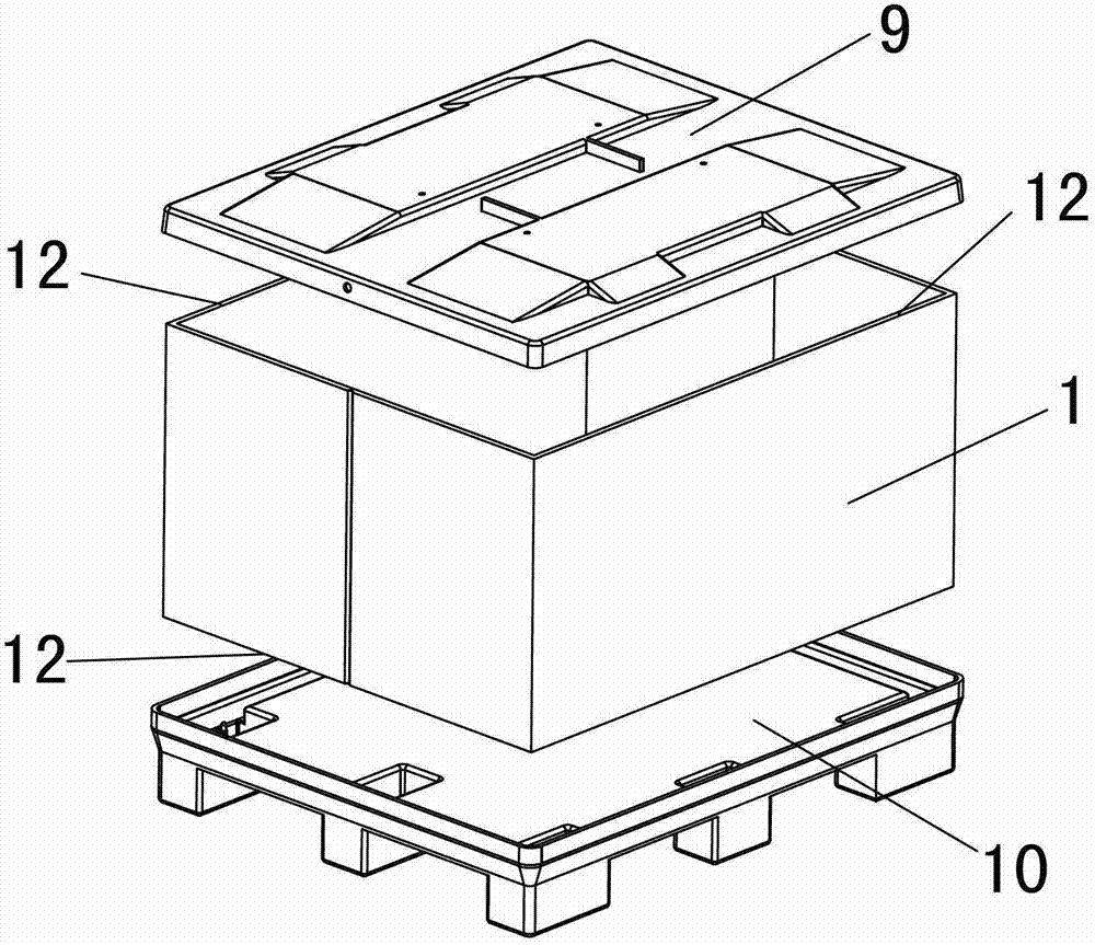
[0034] See attached Figure 4 ~ attached Figure 6 As shown, a feeding device including a fuselage 15 and a conveying coaming 1, on the moving track of the coaming 1, a heating device, a crimping wheel assembly and an edge trimming device are sequentially arranged along the moving direction of the coaming 1; wherein:

[0035] The feeding device is composed of two pairs of traction rollers 2, two traction rollers 2 in each pair of traction rollers 2 are located on both sides of the coaming 1, the distance between the two traction rollers 2 is less than the thickness of the coaming 1, and at least one The root traction roller 2 is connected with the output shaft of a motor, and the coaming 1 is sent out through the static friction between the traction roller 2 and the coaming 1, and the distance between the two traction rollers 2 can be adjusted according to the width of the coam...

Embodiment 2

[0044] Embodiment 2: Double side edge banding structure of the coaming panel edge banding machine

[0045] See attached Figure 8 ~ attached Figure 10 As shown, a feeding device including a fuselage 15 and a conveying coaming 1, on the moving track of the coaming 1, a heating device 3, a crimping wheel assembly and an edge trimming device are sequentially arranged along its moving direction; wherein:

[0046] The feeding device is composed of two pairs of traction rollers 2, two traction rollers 2 in each pair of traction rollers 2 are located on both sides of the coaming 1, the distance between the two traction rollers 2 is less than the thickness of the coaming 1, and at least one The root traction roller 2 is connected with the output shaft of a motor, and the coaming 1 is sent out through the static friction between the traction roller 2 and the coaming 1, and the distance between the two traction rollers 2 can be adjusted according to the width of the coaming 1 .

[0...


PUM


Abstract

The invention provides a skirt board edge-banding structure of a skirt board edge-banding machine. The skirt board edge-banding structure is characterized in that two parallel side edges to be machined of a skirt board are respectively provided with a heating device and an edge press wheel component, along the moving direction of the skirt board, the edge press wheel component is arranged in front of the heating device, and the heating device is acted on at least one side surface of the side edge to be machined of the skirt board; and the edge press wheel component consists of a first edge press wheel and a second edge press wheel which are arranged in pair, and the first edge press wheel and the second edge press wheel are respectively arranged at two sides of the side edge to be machined of the skirt board to grind the softened side edge to be machined to deform, so that the surfaces of two sides of the side edge to be machined are glued together, and the edge of the skirt board can be banded.

Description

technical field [0001] The invention relates to processing equipment for a coaming of a coaming box, in particular to a coaming edge sealing structure of a coaming edge banding machine, which is suitable for welding the edge of a coaming box coaming. Background technique [0002] With the establishment of China's socialist market economic system, the acceleration of world economic integration and the rapid development of science and technology, the logistics industry has become an important means to improve market competitiveness and enhance the core competitiveness of enterprises. The turnover box plays an indispensable role in the logistics industry. After years of development, various forms of turnover boxes have emerged. At present, the most widely used is the folding turnover box, which can be folded and stored when it is empty. In order to save space, the coaming box in the folding turnover box is widely promoted because of its light weight, see the attached figure 1 ...

Claims


Application Information

Patent Timeline
Patent Type & Authority Applications(China)
IPC IPC(8): B29C65/02B29C65/78
Inventor 王忠
Owner SUZHOU LIANGCAI LOGISTICS TECH
Why Eureka
Try Eureka