
Fitting method between touch screen module and liquid crystal display module

A liquid crystal screen and touch screen technology, which is applied in the field of lamination of touch screen modules and liquid crystal screen modules, can solve the problems of Newton rings, yield drop, inconvenient maintenance, etc., and achieves simple operation procedures, high qualification rate, and convenient replacement. Effect

Active Publication Date: 2013-07-10
深圳市信濠光电科技股份有限公司
View PDF4 Cites 10 Cited by
  • Summary
  • Abstract
  • Description
  • Claims
  • Application Information

AI Technical Summary

Problems solved by technology

[0002] The touch screen of electronic equipment has been favored by the public. When making this kind of touch screen, it is necessary to bond the touch screen module and the LCD screen module. There are two methods generally used in the prior art. The touch screen module and the LCD module are fully bonded. This method will cause a drop in yield rate during the production process, resulting in the scrapping of the touch screen module and the LCD module, which will lead to an increase in the overall cost of the product. Moreover, this method It will also bring inconvenience to subsequent maintenance; the second is to use double-sided tape to bond, and this bonding method will produce a gap between the touch screen module and the LCD module after bonding, resulting in the user touching the screen. Newton's rings or dense

Method used


Image

  • Fitting method between touch screen module and liquid crystal display module
  • Fitting method between touch screen module and liquid crystal display module
  • Fitting method between touch screen module and liquid crystal display module

Examples


Embodiment Construction

[0015] The technical solution of the present invention will be described in detail below in conjunction with the accompanying drawings and specific embodiments, so as to understand the essence of the present invention more clearly and intuitively.

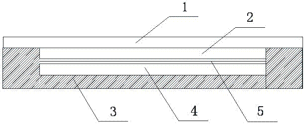
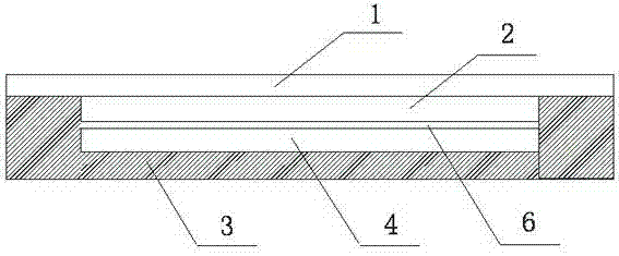
[0016] Such as figure 1 As shown, the touch screen module includes a cover plate 1 and a touch sensor 2 attached to the bottom of the cover plate 1, and a layer of fog film 5 is pasted on the bonding surface of the touch sensor 2 and the liquid crystal screen module 4 or the surface of the liquid crystal screen module 4 , the casing 3 of the electronic equipment is arranged on the lower surface of the liquid crystal screen module 4 and is attached to the cover plate 1 at both ends with double-sided adhesive tape. The surface of the matte film 5 is a micro-grain frosted surface, and this micro-particle frosted surface produces a supporting effect in the gap after the touch screen module and the liquid crystal screen module are bonde...


PUM


Abstract

The invention discloses a fitting method between a touch screen module and a liquid crystal display module. A liquid crystal display module and a touch screen module are arranged, wherein the touch screen module comprises a cover plate and a touch screen sensor fitted with the lower surface of the cover plate. The fitting method is characterized in that a submicroscopic particle layer is arranged between the touch screen module and the liquid crystal display module, and can support a generated tiny gap after the touch screen module and the liquid crystal display module are fitted together. The invention provides two fitting methods for the touch screen module and the liquid crystal display module, aiming at solving problems in the prior art, the submicroscopic particles are arranged between the touch screen module and the liquid crystal display module according to the two methods, and a mutual support action can be generated for the touch screen module and the liquid crystal display module due to the submicroscopic particles, so that a newton ring or the skin packaging generated by the gaps after the touch screen module and the liquid crystal display module are fitted with each other when the touch screen module is operated by an user can be eliminated.

Description

technical field [0001] The invention relates to the technical field of lamination of a touch screen module and a liquid crystal screen module, in particular to a lamination method of a touch screen module and a liquid crystal screen module. Background technique [0002] The touch screen of electronic equipment has been favored by the public. When making this kind of touch screen, it is necessary to bond the touch screen module and the LCD screen module. There are two methods generally used in the prior art. The touch screen module and the LCD module are fully bonded. This method will cause a drop in yield rate during the production process, resulting in the scrapping of the touch screen module and the LCD module, which will lead to an increase in the overall cost of the product. Moreover, this method It will also bring inconvenience to subsequent maintenance; the second is to use double-sided tape to bond, and this bonding method will produce a gap between the touch ...

Claims


Application Information

Patent Timeline
IPC IPC(8): B32B5/16G06F3/041G02F1/1333
Inventor 王大宇
Owner 深圳市信濠光电科技股份有限公司
Learn More