Method for shoring prestressed double-row-pile strong-constraint deep foundation pit

A deep foundation pit support, prestressed technology, applied in excavation, foundation structure engineering, water conservancy engineering, etc. To achieve the effect of improving the stability against overturning, reducing the distance between pile rows and increasing the anti-overturning moment

Inactive Publication Date: 2013-07-10
BEIJING UNIV OF TECH
View PDF5 Cites 18 Cited by
  • Summary
  • Abstract
  • Description
  • Claims
  • Application Information

AI Technical Summary

Problems solved by technology

[0003] The above three foundation pit support schemes have their own limitations and are not applicable in some specific environments: (1) The method of rowing piles and prestressed anchor cables requires that the foundation of surrounding buildings should not be too deep, otherwise the anchor cables will It cannot be constructed; the (2) row of piles plus internal support method requires a narrow and long foundation pit, and the direction of steel support should not be too wide, otherwise the deflection of the steel support will be too large; the (3) double-row pile method, in the foundation pit In the case of deep and strict deformation requirements of adjacent buildings, the horizontal stiffness and anti-overturning capacity of the retaining structure cannot meet the deformation requirements

Method used


Image

  • Method for shoring prestressed double-row-pile strong-constraint deep foundation pit
  • Method for shoring prestressed double-row-pile strong-constraint deep foundation pit

Examples


Embodiment Construction

[0015] Below in conjunction with accompanying drawing and specific embodiment the present invention will be further described:

[0016] 1. Construction steps:

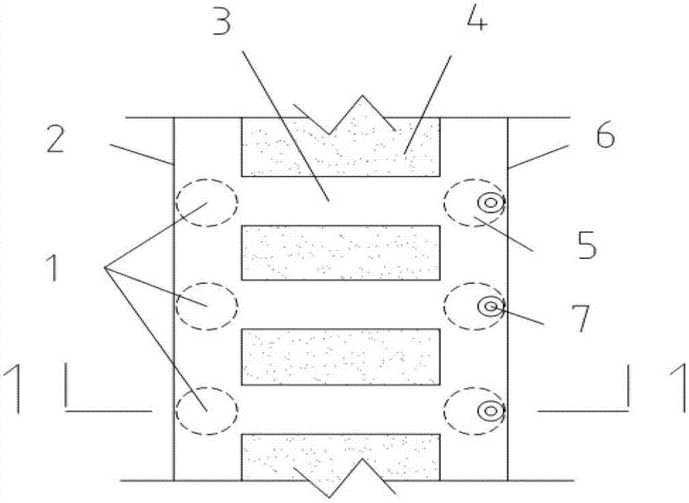
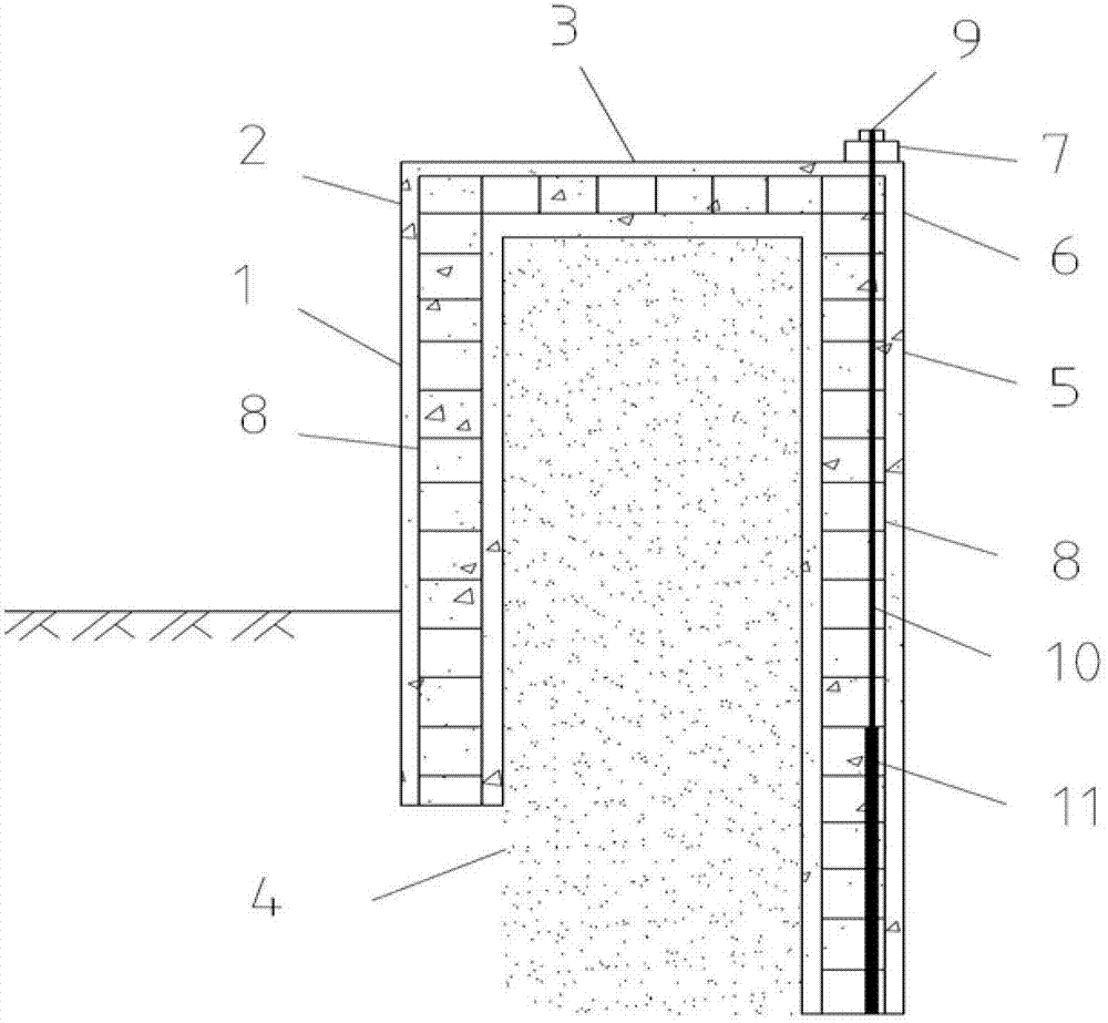
[0017] Arrange two rows of reinforced concrete cast-in-situ piles around the foundation pit to be excavated. The back row of piles 5 and the front row of piles 1 are separated by 3-5 times the pile diameter d, and the back row of piles 5 is 3-5m longer than the front row of piles 1. During the construction of the rear row of piles 5, the prestressed anchor cable 9 is divided into two parts: one part is the free section 10 of the anchor cable, which is triple-corroded with butter, film and bellows, and made to expand and contract freely; the other part is the anchor section 11 of the anchor cable. Without any treatment, the prestressed anchor cables 9 and the reinforcement cages 8 are tied together and then sent into the pile holes for grouting. The prestressed anchor cables are arranged in the direction close to the ex...


PUM


Abstract

The invention discloses a method for shoring a prestressed double-row-pile strong-constraint deep foundation pit and belongs to the technical field of civil engineering construction. The method comprises that two rows of reinforced concrete cast-in-place piles are arranged successively on the periphery of the foundation pit to be excavated, one row of reinforced concrete cast-in-place piles, which are close to the foundation pit, serve as front row piles, and the other row of reinforced concrete cast-in-place piles, which are close to existing buildings, serve as rear row piles; front row piles are formed through concrete pouring of reinforcing cages, and rear row piles are formed through concrete pouring after binding and planting prestressed anchor cables and reinforcing cages into pile holes; one ends of prestressed anchor cables, which are close to the ground, are anchor cable free sections, and anticorrosion is conducted on outer surfaces through grease, thin films and bellows, so that prestressed anchor cables can extend and retract freely; and prestressed anchor cables and reinforcing cages are bound and placed into pile holes through anchor cable anchoring sections at the other ends before grouting, front row pile top beams, rear row pile top beams and coupling beams are poured, and anchor cable anchoring pads which exert the prestressing force on prestressed anchor cables are arranged on rear row pile top beams. By the aid of the method, the horizontal stiffness and the pit overturning stability of a shoring structure can be improved, and security coefficients of peripheral buildings can be improved.

Description

technical field [0001] The invention belongs to the technical field of civil engineering construction, and is mainly used for foundation pit support projects adjacent to important buildings and unable to be anchored and internally supported. Background technique [0002] During the excavation of urban foundation pits, since there are many existing buildings around the foundation pits, and the foundations of the buildings are relatively deep, excavation on slopes is not allowed. In order to ensure the stability of the foundation pit and limit the level of the soil around the foundation pit Displacement and settlement must adopt a suitable foundation pit support scheme. Commonly used foundation pit support methods in practice include: (1) pile row plus prestressed anchor cable method. That is to lay a row of reinforced concrete piles around the foundation pit first, then excavate the soil step by step, and apply prestressed anchor cables at the design depth to limit the horizo...

Claims


Application Information

Patent Timeline
Patent Type & Authority Applications(China)
IPC IPC(8): E02D17/04E02D29/02
Inventor 姚爱军王成王强翟玉新田治州
Owner BEIJING UNIV OF TECH
Why Eureka
Try Eureka