Prefabricated reinforced concrete frame structure system

A technology of reinforced concrete and frame structure, which is applied to building components, building structure, earthquake resistance, etc., can solve problems such as poor seismic performance, and achieve the effects of easy transportation, simple form, and accelerated construction speed.

Active Publication Date: 2013-07-10
CHINA RAILWAY CONSTR GROUP +1
View PDF6 Cites 41 Cited by
  • Summary
  • Abstract
  • Description
  • Claims
  • Application Information

AI Technical Summary

Problems solved by technology

[0003] The purpose of the present invention is to overcome the shortcomings of poor seismic performance of the existing prefabricated frame structures, and propose a new prefabricated reinforced concrete frame structur

Method used


Image

  • Prefabricated reinforced concrete frame structure system
  • Prefabricated reinforced concrete frame structure system
  • Prefabricated reinforced concrete frame structure system

Examples


Embodiment 1

[0034] The invention is applied to a beam-in-connection assembled reinforced concrete frame structure.

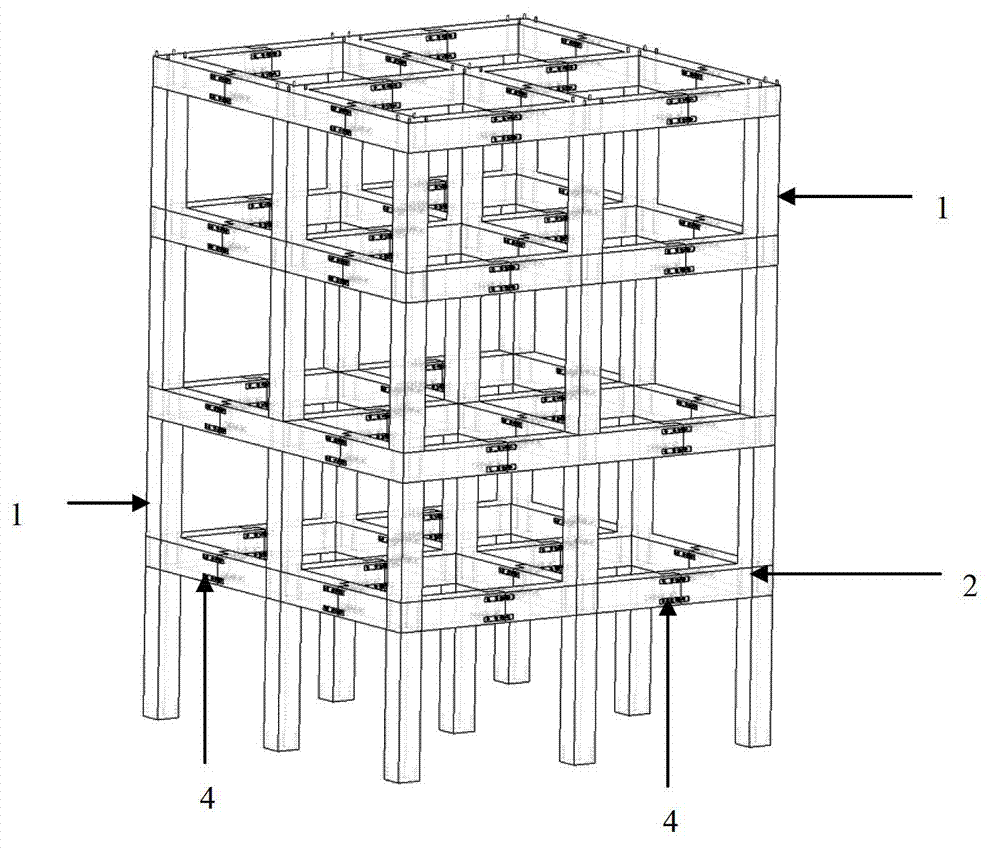
[0035] Such as figure 1 and 2 Shown: a prefabricated reinforced concrete frame structure system, including prefabricated column 1 and beam structure, the beam structure is a prefabricated structure connected in the beam;

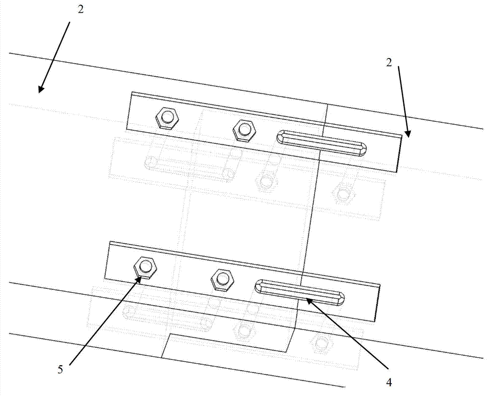
[0036]The connecting assembled structure in the beam includes prefabricated special-shaped beam 2, U-shaped bolt 4 and nut 5. The prefabricated special-shaped beam 2 is a prefabricated reinforced concrete member, and the prefabricated special-shaped beam 2 is reserved in the middle of the prefabricated column 1. The cross-section width at the edge of the prefabricated special-shaped beam 2 is reduced by half, and the edge of the prefabricated special-shaped beam 2 is left with a through transverse channel, and the U-shaped bolt 4 passes through the reserved space of the adjacent prefabricated special-shaped beam 2 The transverse channels are connected a...

Embodiment 2

[0041] The invention is applied to beam end connection assembled reinforced concrete frame structures.

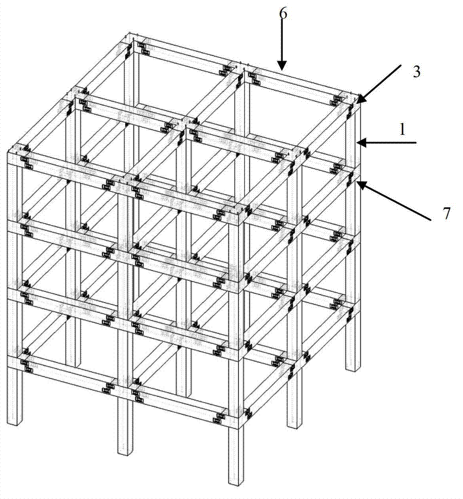
[0042] Such as image 3 and 4 As shown, a prefabricated reinforced concrete frame structure system includes prefabricated columns 1 and a beam structure, and the beam structure is a beam end connection assembly structure;

[0043] The prefabricated beam end connection structure includes node splicing devices 3, nuts 5, prefabricated beams 6, energy dissipation connecting plates 7 and pre-embedded transverse bolts 8, the node splicing devices 3 and prefabricated beams 6 are prefabricated reinforced concrete components, and the The node splicing device 3 is reserved with a vertical channel through which the reserved steel bar of the prefabricated column 1 passes, and the beam height at the edge of the beam end of the node splicing device 3 and the prefabricated beam 6 is reduced by half, and the node splicing device 3 and the prefabricated There are pre-embedded transverse ...


PUM


Abstract

The invention discloses a prefabricated reinforced concrete frame structure system. The system comprises a prefabricated column and beam structures, wherein the beam structures comprise a beam middle connecting prefabricated structure and a beam end connecting prefabricated structure; the beam middle connecting prefabricated structure comprises a prefabricated special-shaped beam, a U-shaped bolt and a nut; the beam end connecting prefabricated structure comprises a node splicing device, a nut, a prefabricated beam, a dissipation connecting plate and an embedded lateral bolt; reinforcing steel bars are reserved at the upper end of the prefabricated column, a vertical hole path is reserved at the lower end of the prefabricated column, and the prefabricated column, a foundation and the prefabricated special-shaped beam or the node splicing device are connected into a whole. Standardized production of the prefabricated column, the prefabricated special-shaped beam, the node splicing device and the prefabricated beam can be performed in factories, wet construction in construction fields is avoided, and the house building speed is accelerated. Forms of all prefabricated parts are relatively simple, transportation is facilitated, and the dissipation capacity of the prefabricated structure is improved due to use of the dissipation connecting plate.

Description

technical field [0001] The invention relates to an assembled reinforced concrete frame structure system, which is mainly suitable for multi-story assembled reinforced concrete frame structures in earthquake-prone areas. Background technique [0002] The prefabricated reinforced concrete structure refers to the standardized production of various components of the structure, including prefabricated columns, prefabricated beams, prefabricated floors, prefabricated shear walls, etc. The structure formed by splicing and connecting. The prefabricated reinforced concrete structure has the advantages of saving labor force, fast construction progress, helping to realize building energy saving, and facilitating industrial production and mechanized construction. However, the integrity and stiffness of ordinary prefabricated reinforced concrete structures are lower than those of cast-in-place reinforced concrete structures, so the seismic performance of ordinary prefabricated reinforce...

Claims


Application Information

Patent Timeline
IPC IPC(8): E04B1/58E04B1/98E04B1/19
Inventor 贾洪李爱群王维周德恒潘志宏
Owner CHINA RAILWAY CONSTR GROUP
Why Eureka
Try Eureka