
Automatic monitoring method of concrete casting vibrating blank layer

A technology of pouring vibration and automatic monitoring, which is applied in the fields of construction, building structure, and building material processing, and can solve the problems of unavoidable leakage vibration, difficulty in obtaining blank layer coverage time leakage vibration, over vibration, under vibration, single billet Layer vibration quality control is rough and other problems, to avoid the effect of vibration leakage

Active Publication Date: 2013-07-10
POWERCHINA CHENGDU ENG
View PDF4 Cites 27 Cited by
  • Summary
  • Abstract
  • Description
  • Claims
  • Application Information

AI Technical Summary

Problems solved by technology

In traditional concrete vibration quality control, the identification of the concrete pouring and vibrating base layer is carried out through manual spot check records, but in actual operation, only the construction process of the tile method is recorded to identify the pouring and vibrating base layer, and the covering time of the base layer The average coverage time of the entire base layer is derived from a rough estimate. The vibration quality control of a single base layer is relatively rough, and it is difficult to avoid the phenomenon of missing vibration; and for the step method construction process, the identification of the pouring and vibrating base layer and the vibration of a single base layer The quality control is weakened, it is more difficult to obtain the covering time of the billet layer, and it is difficult to avoid the phenomenon of missing vibration, over vibration and under vibration

Method used


Image

  • Automatic monitoring method of concrete casting vibrating blank layer
  • Automatic monitoring method of concrete casting vibrating blank layer

Examples


Embodiment

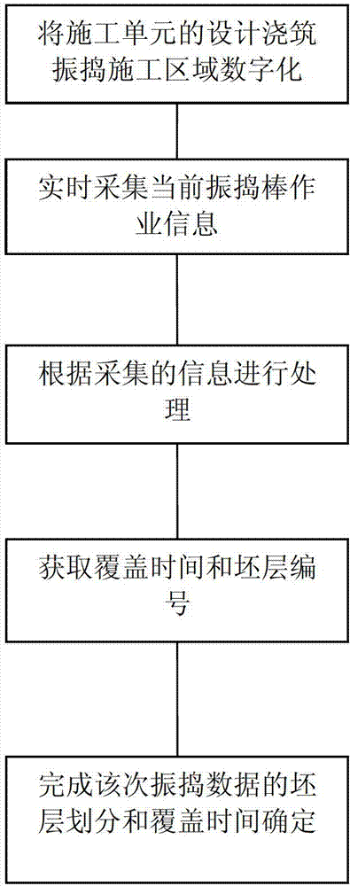
[0021] Such as figure 1 As shown, the main process of this example is to first digitize the design, pouring and vibrating construction area of ​​the construction unit, and then collect the current vibrating bar operation information in real time, and perform calculation and processing based on the collected information to obtain the coverage time and base layer number, so that Complete the layer division and coverage time determination of the vibration data.

[0022] The specific process is:

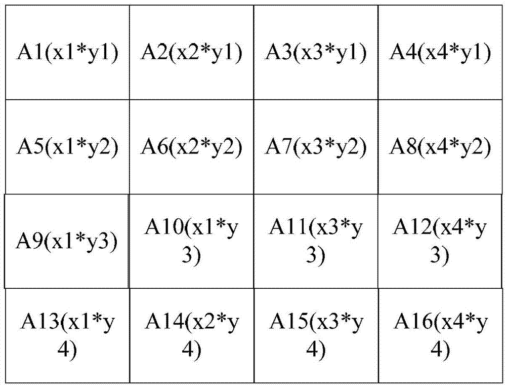
[0023] First, before starting to vibrate, digitize the design pouring and vibrating construction area of ​​the construction unit, divide the area equally according to a certain interval (for example, the influence range of the vibrating rod is 0.75m*0.75m), and obtain the vibrating area lattice A(m*n), such as figure 2 As shown, and given lattice coordinate information (Xa, Ya), this example divides A1 (x1, y1) - A16 (x4, y4) a total of 16 squares with the same area, and at the same t...


PUM


Abstract

The invention relates to the field of vibrating quality control in concrete casting construction of the hydraulic and hydroelectric engineering, in particular to an automatic monitoring method of a concrete casting vibrating blank layer obtained by a laying method or a step method casting process in mass concrete vibrating quality control of the hydraulic and hydroelectric engineering. The method comprises main steps as follows: firstly, a designed casting vibrating construction area of a construction unit is digitalized; then, current operation information of a vibrating needle is acquired in real time; computing is performed according to the acquired information; cover time and a blank layer number are obtained; and accordingly blank layer dividing and cover time determining of vibrating data for the time are completed. The automatic monitoring method has the benefits that the concrete casting vibrating blank layer is automatically identified, vibration monitoring data are divided into the blank layer automatically, concrete cover time in any position can be obtained, an effective vibrating area of the blank area is judged, and accordingly quality problems caused by miss vibrating, lack vibrating, over vibrating and the like are effectively solved. The automatic monitoring method is particularly applicable to mass concrete vibrating quality control of the hydraulic and hydroelectric engineering.

Description

technical field [0001] The invention relates to the field of vibrating quality control in the concrete pouring construction of water conservancy and hydropower projects, in particular to a method for automatically monitoring the pouring and vibrating base layer of the tiling method or step method pouring process in the vibrating quality control of large-volume concrete in water conservancy and hydropower projects. Background technique [0002] Concrete vibration is the key process of concrete pouring, and the monitoring and control of vibration quality in the process is one of the important links of concrete quality control. At present, in the vibrating construction on the construction site, the staggered insertion of the vibrating rods is used to ensure the full coverage of the concrete pouring area. Most of the extensive empirical methods are used to control the insertion depth, insertion angle, vibrating duration, vibrating spacing, and coverage time of the vibrating rods....

Claims


Application Information

Patent Timeline
IPC IPC(8): E04G21/08
Inventor 王仁坤余挺钟桂良赖刚尹习双
Owner POWERCHINA CHENGDU ENG
Learn More