

Clutch fork with socket structure
A clutch fork and socket technology, applied in the clutch field, can solve the problems of increased wear of the support ball and socket, customer complaints, failure to achieve dustproof effect, etc., to eliminate sharp abnormal noise and solve limit effect of the problem
Inactive Publication Date: 2013-07-10
JIANGLING MOTORS
View PDF6 Cites 2 Cited by
- Summary
- Abstract
- Description
- Claims
- Application Information
AI Technical Summary
Problems solved by technology
The disadvantage of the existing clutch is that when the socket of the shift fork is matched with the support ball, its relative movement will cause the soft grease to flow out of the socket, thereby aggravating the wear of the support ball and the socket, and its relative movement will produce sharp abnormalities. The sound caused customers to complain; although the practical shift fork limit piece and rivet can limit the shift fork to support the ball head, it needs to process two rivet holes and the limit piece, which is costly and practical for a long time. The limiting effect of the sheet will degrade; and this technology fails to achieve dustproof effect
Method used
View moreImage
Smart ImageViewing Examples

Examples
Embodiment
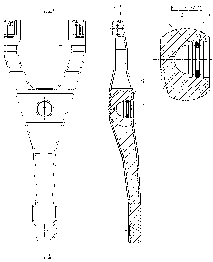
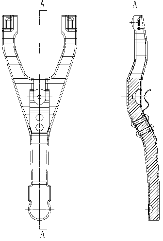
[0014] Example: see figure 1 , figure 2 .
[0015] A clutch shift fork with dimple structure, in which an oil groove 1 is added in the dimple of the clutch shift fork.
[0016] The oil tank 1 is an annular oil tank.
[0017] There are two annular oil grooves.
[0018] Add a rubber sealing ring 2 in the annular oil groove near the outside.
[0019] The inner diameter of the rubber sealing ring 2 is the same as the outer diameter of the support ball head.
Login to View More PUM
 Abstract
The invention relates to the field of clutches, in particular to a clutch fork with a socket structure. Two oil grooves are added in a socket of the clutch fork and shaped in circular rings, a rubber sealing ring is added in the oil groove, shaped in the circular ring, close to the outside, and the inner diameter of the rubber sealing ring is identical with the outer diameter of a rod portion of a supporting ball head. The clutch fork with the socket structure has the advantages that 1, the problem of abrasion of the supporting ball head and the socket caused by the fact that lubricating grease flows out of the fork socket when the fork socket is matched with the supporting ball head is solved; 2, shrill abnormal sound generated by relative rotation of the supporting ball head and the fork socket is eliminated; 3, the problem of limiting of a fork ball head is solved; and 4, the problem that outside pollutants enter the socket of the fork is solved.
Description
technical field [0001] The invention relates to the field of clutches, in particular to a clutch shift fork with a dimple structure. Background technique [0002] When the clutch pedal is pressed to release the clutch, the push rod of the sub-cylinder pushes the shift fork, supported by the support ball head, and the upper end of the shift fork presses the release bearing, so that the diaphragm spring returns to its original position, and the clutch pressure plate is separated from the driven plate. That is, the clutch disengages. The disadvantage of the existing clutch is that when the socket of the shift fork is matched with the support ball, its relative movement will cause the soft grease to flow out of the socket, thereby aggravating the wear of the support ball and the socket, and its relative movement will produce sharp abnormalities. The sound caused customers to complain; although the practical shift fork limit piece and rivet can limit the shift fork to support th...
Claims
Login to View More Application Information
Patent Timeline
 IPC IPC(8): F16D23/12
Inventor胡禄生张天乐朱金华
OwnerJIANGLING MOTORS