
Bias gear speed changing shaft

A technology of shifting shafts and gears, applied in gear transmissions, belts/chains/gears, components with teeth, etc., can solve the problems of single function and poor adaptability, and achieve long service life, simple manufacturing, and debugging. handy effect

Inactive Publication Date: 2013-07-10
钟婕
View PDF5 Cites 1 Cited by
  • Summary
  • Abstract
  • Description
  • Claims
  • Application Information

AI Technical Summary

Problems solved by technology

[0005] The purpose of the present invention is to overcome the shortcomings of the current known gear transmission shafts such as single function and poor adaptability, and provide the public with a unique gear transmission component

Method used


Image

  • Bias gear speed changing shaft
  • Bias gear speed changing shaft
  • Bias gear speed changing shaft

Examples


Embodiment Construction

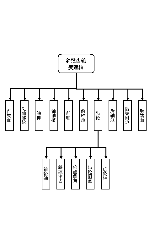
[0029] As a technical solution for product manufacturing, the present invention can make the solution concretely implemented through the organic combination of corresponding components. The product organization structure of an embodiment of the present invention is as follows: figure 1 shown.

[0030] figure 1 Among them, the embodiment product is formed by the combination of ten components: front end face, shaft extension thread, shaft extension, shaft pin groove, front axle, front journal, gear, rear journal, rear end hypotenuse, and rear end face, among which the gear The component also includes five small components of the front axle, twill gear teeth, gear tooth chamfer, gear rounding, and rear axle.

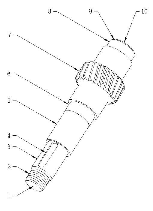
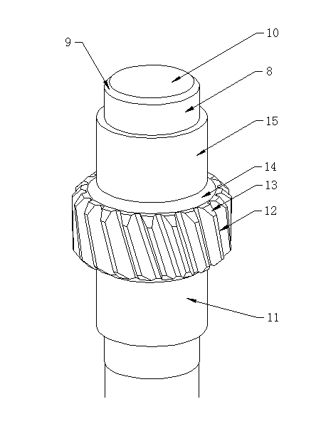
[0031] In the embodiment, the structural shape of the product entity and the mutual positional relationship between its various components, such as figure 2 shown.

[0032] figure 2 Among them, the structure of the product includes front end face (1), shaft exten...


PUM

PropertyMeasurementUnit
Inclinationaaaaaaaaaa

Abstract

The invention relates to a gear shaft, in particular to a bias gear speed changing shaft which can be not only used independently and but also used in a group array. Ten components including a front end surface, a shaft extension thread, a shaft extension, a shaft pin groove, a front shaft, a front shaft neck, a gear, a back shaft neck, a back end bevel edge and a back end surface are combined to form the bias gear speed changing shaft. The gear comprises five small components including a front wheel spindle, bias gear teeth, gear teeth chamfers, a gear rounding and a back wheel spindle. Besides the same advantages of the common gear speed changing shafts, the bias gear speed changing shaft further has the advantages of accurate match, long service life, convenience in debugging, adaptability and the like as compared with common gear speed changing shafts; and the bias gear speed changing shaft is easy and convenient to produce, and has a solid and durable structure, wide marketing space, certain social application value and economical additional value.

Description

technical field [0001] The invention relates to a gear shaft, in particular to a helical gear transmission shaft which can be used alone or in a group array. Background technique [0002] The gear transmission shaft refers to a metal rotating shaft with gears for changing the speed. [0003] The gear transmission shaft is one of the necessary parts of the rotary working tool. The gear teeth of the known gear transmission shaft generally adopt the straight grain form, that is, the centerline of the gear teeth is parallel to the axis centerline of the rotation shaft. The inclination angle between them is 0°. Although the known gear transmission shaft has the characteristics of simple manufacture, convenient maintenance, and quick installation, it also has a fatal feature: when it is used in a group array, there is a large gap between the gear teeth, the vibration is large during power transmission, and the service life is long. It is short, and the variable speed step is une...

Claims


Application Information

Patent Timeline
IPC IPC(8): F16H55/02F16H3/00
Inventor 钟婕
Owner 钟婕
Learn More