
Device and method for detecting shape error accuracy of non-contact rotary parts

A non-contact technology for rotary parts, applied in the field of non-contact rotary parts shape error precision detection devices, can solve the problems of high environmental requirements, low detection efficiency, high labor intensity, etc., and achieve low environmental requirements, good detection effect, The effect of low detection cost

Active Publication Date: 2015-11-18
NINGBO INST OF TECH ZHEJIANG UNIV ZHEJIANG
View PDF7 Cites 2 Cited by
  • Summary
  • Abstract
  • Description
  • Claims
  • Application Information

AI Technical Summary

Problems solved by technology

[0003] In the process of workpiece shape and position error detection in the prior art, most of them still use manual methods to complete various shape and position accuracy detection by rotating the workpiece, which has high labor intensity, low work efficiency, and poor reliability of detection results.
However, with the rapid development of computer technology, the detection methods are undergoing qualitative changes. At present, most of them have started to use three-coordinate measuring machines or tool microscopes, but such equipment is expensive, complicated to operate, high in environmental requirements, and low in detection efficiency. , and because this type of equipment is generally a contact measurement, it is easy to damage the probe or scratch the surface of the measured entity, and this type of equipment is not suitable for the measurement of the surface of flexible material products, because when the penetration touches the surface of the workpiece to be measured, it will change the object Therefore, in actual production, it is more and more urgent to provide corresponding special equipment for the detection of shape and position errors of workpieces.

Method used

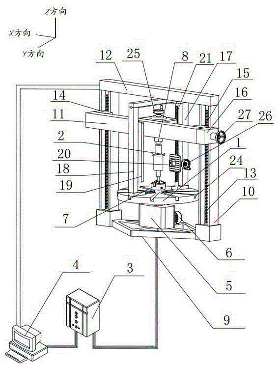

Image

  • Device and method for detecting shape error accuracy of non-contact rotary parts
  • Device and method for detecting shape error accuracy of non-contact rotary parts
  • Device and method for detecting shape error accuracy of non-contact rotary parts

Examples


Embodiment Construction

[0036] The present invention will be further described below in conjunction with accompanying drawing and specific embodiment:

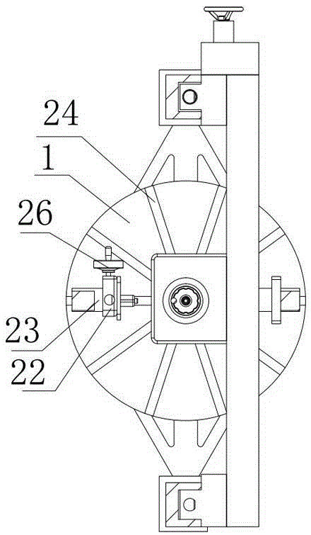
[0037] Such as figure 1 , 2 Shown: a non-contact rotary part shape error accuracy detection device, which includes a worktable 1, set on the worktable 1 for fixing the workpiece 2 to be measured and driving the workpiece 2 to be measured to rotate axially along the Z direction. device, an information acquisition device installed on the workbench 1 that can be adjusted in the Y direction and Z direction and used to obtain the shape and position information of the workpiece 2 to be measured, an adjustment device for the elastic clamping device, a controller 3 and a computer 4, The clamping device, the information obtaining device and the adjusting device are all electrically connected to the controller 3 , and the controller 3 and the information obtaining device are also electrically connected to the computer 4 .

[0038] The clamping device include...


PUM


Abstract

The invention relates to the field of mechanical manufacturing, in particular to a non-contact type rotation part shape error precision detection device and a detection method. The detection device comprises a worktable (1), a clamping device, an obtaining device, an adjusting device, a controller (3) and a computer (4), wherein the clamping device is arranged on the worktable (1) and used for fixing a workpiece (2) to be detected and driving the workpiece (2) to be detected to rotate axially in the Z direction, the obtaining device is arranged on the worktable (1), can be adjusted in the Y direction and the Z direction and is used for obtaining the shape information of the workpiece (2) to be detected, and the adjusting device is used for loosening and clamping the clamping device. The clamping device, the information obtaining device and the adjusting device are respectively and electrically connected with the controller (3). The controller (3) and the information obtaining device are electrically connected with the computer (4). The detection device is low in price, easy to operate, low in requirement on environment and high in detection efficiency, and the detection method is good in detection effect.

Description

technical field [0001] The invention relates to the field of mechanical manufacturing, in particular to a non-contact detection device and method for shape error accuracy of rotating parts. Background technique [0002] With the rapid development of manufacturing technology in industrial fields such as automobiles, machine tools, home appliances, and aviation, and the increasing requirements of customers for product quality, the inspection link in the product manufacturing process has become more and more important. The reasonable establishment of tolerances in the part design process and the correct detection of tolerances in the manufacturing process are crucial to the quality of the product. Among them, the shape and position error is an important technical index to evaluate the manufacturing quality of parts. Especially in precision machinery, instrumentation, aerospace and various high-tech equipment, the shape and position errors of parts are often the key to the work...

Claims


Application Information

Patent Timeline
Patent Type & Authority Patents(China)
IPC IPC(8): G01B11/24
Inventor 张学昌梁涛章少剑张雷唐艳梅汪磊
Owner NINGBO INST OF TECH ZHEJIANG UNIV ZHEJIANG
Learn More