Displacement amplification device

A technology of amplifying device and displacement, applied in the direction of using fluid device to transmit sensing components, etc., can solve the problems of large installation space, high cost, complex structure, etc., and achieve the effect of cost saving, simple structure and strong applicability

Inactive Publication Date: 2013-07-10
HARBIN INST OF TECH
View PDF6 Cites 5 Cited by
  • Summary
  • Abstract
  • Description
  • Claims
  • Application Information

AI Technical Summary

Problems solved by technology

[0003] In order to solve the problems of complex structure, high cost and large installation space occupied by the displacement amplifying mechanism and other devices in the prior art, the present invention further provides a displacement amplifying device

Method used


Image

  • Displacement amplification device

Examples


specific Embodiment approach 1

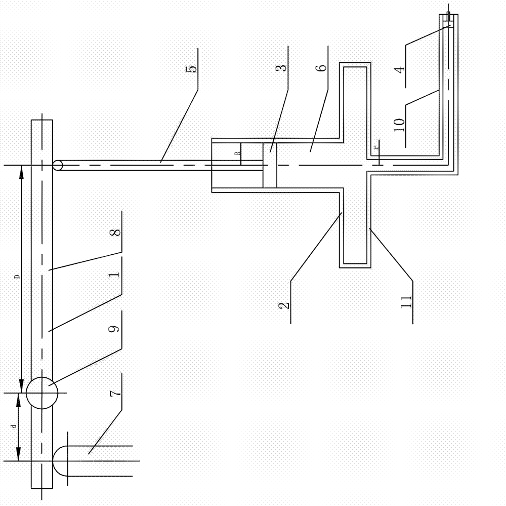
[0007] Specific implementation mode one: combine figure 1 Describe a displacement amplifying device in this embodiment, the device includes a lever structure 1 and a hydraulic cylinder mechanism 2, the lever structure 1 includes a top column 7, a lever 8 and a support shaft 9, and the hydraulic cylinder mechanism 2 includes a first piston 3, a second Two piston 4, connecting rod 5, hydraulic oil 6, hydraulic cylinder 11 and oil outlet pipe 10; the cross section of hydraulic cylinder 11 is an inverted 'T' shape, the cross section of oil outlet pipe 10 is 'L' shape, and the lever 8 passes through Support shaft 9, and the axis of lever 8 is perpendicular to the axis of support shaft 9, the upper end of push column 7 is arranged below the left end of lever 8, the upper end of hydraulic cylinder 11 is open, and one end of oil outlet pipe 10 is in the middle of the lower end surface of hydraulic cylinder 11 Sealed communication, the inner radius R of the upper part of the hydraulic ...

specific Embodiment approach 2

[0008] Specific implementation mode two: combination figure 1 Describe a displacement amplification device in this embodiment, the distance D from the intersection point of the lever 8 and the support shaft 9 to the connecting rod 5 is two to twenty times the distance d from the intersection point of the lever 8 and the support shaft 9 to the top column 7 , through the lever structure 1, the displacement of the right end of the lever 8 to the connecting rod 5 is increased by two to twenty times compared with the displacement of the push column 7, and the others are the same as in the first embodiment.

specific Embodiment approach 3

[0009] Specific implementation mode three: combination figure 1 Describe a displacement amplification device in this embodiment, the inner radius R of the upper part of the hydraulic cylinder 11 is two to ten times the radius r of the oil outlet pipe 10, and the displacement of the second piston 4 moving to the right through the hydraulic cylinder mechanism 2 is the second Two to ten times the displacement of the downward movement of the piston 3, and the others are the same as in the first embodiment.

[0010] working principle

[0011] When the present invention works, push the top column 7 to move upward, the top column 7 drives the left end of the lever 8 to move upward, and the right end of the lever 8 moves downward through the principle of leverage, and then pushes the first piston 3 to move downward. Since the hydraulic oil 6 is incompressible, Push the piston 4 to move to the right, and the displacement of the second piston to the right is more than four times the di...


PUM


Abstract

The invention relates to a displacement amplification device, and aims at resolving the problems that a device in the prior art is complex in structure and high in cost, and occupied installation space by a displacement amplification mechanism and other devices is large. The displacement amplification device comprises a lever structure and a hydraulic cylinder mechanism, wherein the lever structure comprises an ejection column, a lever and a support shaft; and the hydraulic cylinder mechanism comprises a first piston, a second piston, a connecting rod, hydraulic oil, a hydraulic cylinder and an oil outlet tube. The lever penetrates through the support shaft, the axis of the lever is vertical to the axis of the support shaft, the upper end of the ejection column is arranged below the left end of the lever, one end of the oil outlet tube is communicated with the middle portion of the lower end face of the hydraulic cylinder in a sealed mode, the lower end of the connecting rod is fixedly connected with the upper end face of the first piston, the first piston is arranged in a cylinder body of the hydraulic cylinder, the upper end of the connecting rod is arranged below the right end of the lever, the second piston is arranged in the other end of the oil outlet tube, and hydraulic oil is filled both in the hydraulic cylinder and the oil outlet tube. The displacement amplification device is used in the field of mechanical tools.

Description

technical field [0001] The invention relates to a displacement amplification device. Background technique [0002] At present, the commonly used methods of displacement amplification devices include lever amplification, gear mesh amplification, flexible hinge amplification, and multi-stage screw lever mechanism amplification. Disadvantages of the prior art: high device loss, complicated structure, high cost, and difficult placement of the displacement amplification mechanism, other sensing devices and output devices. Contents of the invention [0003] In order to solve the problems of complex structure, high cost and large installation space occupied by the displacement amplification mechanism and other devices in the prior art, the present invention further provides a displacement amplification device. [0004] The technical solution adopted by the present invention to solve the above problems is: the device includes a lever structure and a hydraulic cylinder mechanism, ...

Claims


Application Information

Patent Timeline
Patent Type & Authority Applications(China)
IPC IPC(8): G01D5/60
Inventor 申岩郭志忠于文斌张国庆路忠峰
Owner HARBIN INST OF TECH
Why Eureka
Try Eureka