Weight-in-motion system for vehicles and weighing method thereof
A dynamic weighing system and vehicle technology, applied in the vehicle weighing system and its weighing field, can solve the problems of inability to judge the driving state of the vehicle, affecting the weighing inspection work of the vehicle, and inability to judge abnormal driving, etc. The effect of accurate weight and easy analysis
- Summary
- Abstract
- Description
- Claims
- Application Information
AI Technical Summary
Problems solved by technology
Method used
Image
Examples
Embodiment 1
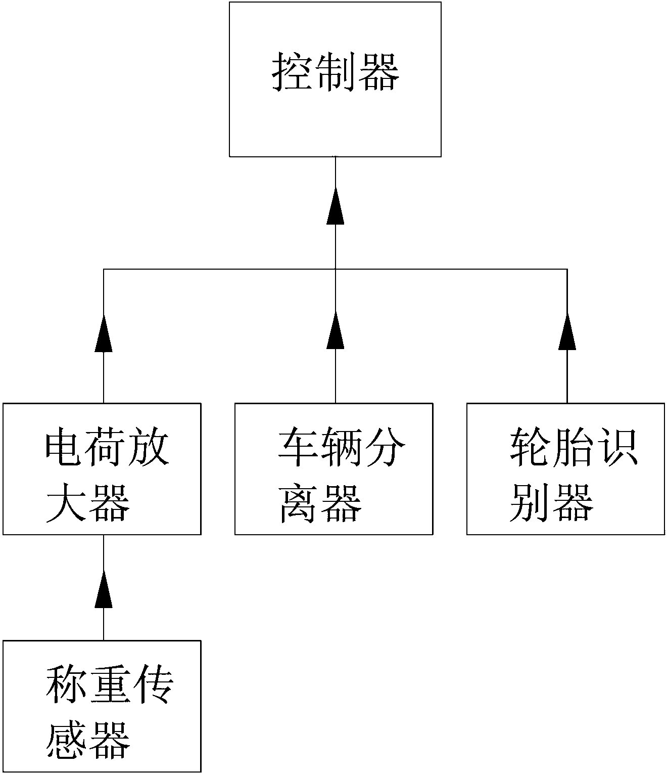
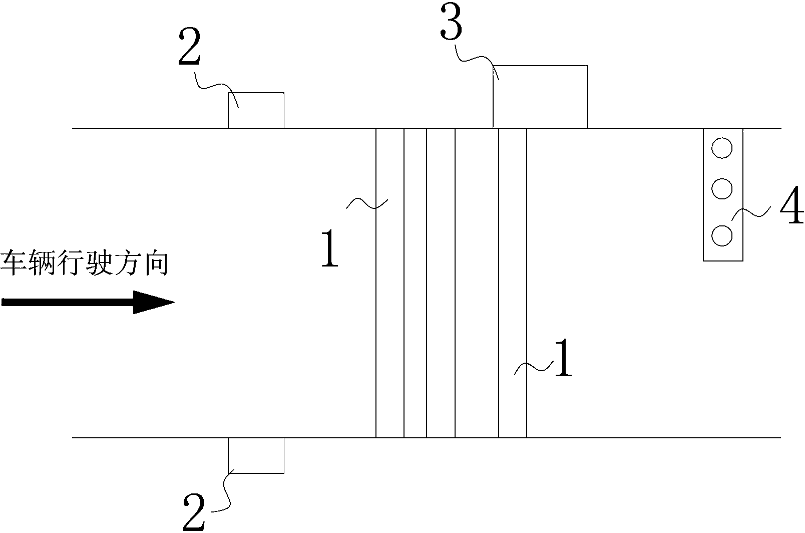
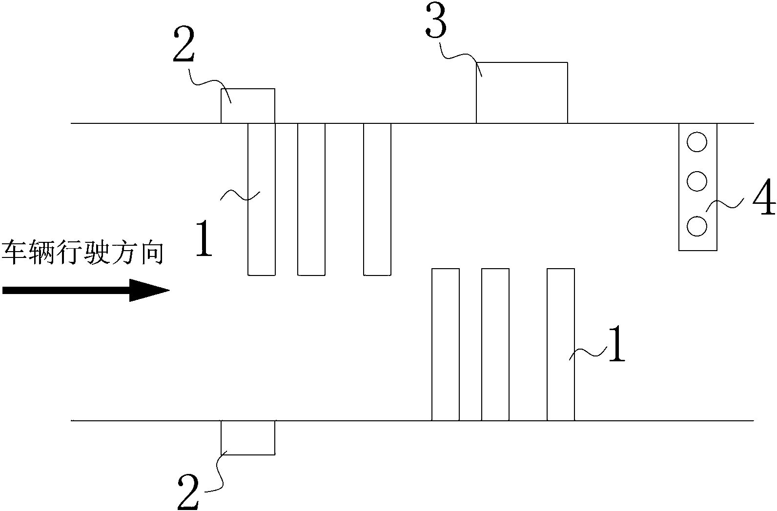
[0058] Such as figure 1 and figure 2 As shown, a vehicle dynamic weighing system and weighing method thereof, it includes a controller 3, a tire identifier 4, a vehicle separator 2 and m wheel load weighing sensors 1, wherein the controller is connected to the The vehicle separator 2 is used to collect separation information between the measured vehicles; the wheel load weighing sensor 1 is a vehicle dynamic weighing piezoelectric sensor, and the vehicle dynamic weighing piezoelectric sensor is connected to the controller through a charge amplifier; The tire identifier is a piezoelectric tire identification sensor, and the controller 3 is connected to the tire identifier 4 so as to collect tire identification signals and thus determine the type of the vehicle under test; the controller 3 is connected to m wheel weights respectively. The load cell 1 is used to compensate the weighing method or / and abnormal wheel weight information by using abnormal driving data according to t...
Embodiment 2
[0060] Such as figure 2 Shown, a kind of abnormal driving data compensation weighing method of vehicle dynamic weighing system, it comprises the following steps:
[0061] Step 1. Lay m wheel load cells in parallel on the road, and preset the sensor distance between the wheel load cells to be: the sensor distance between the first and second wheel load cells is L 1 , the sensor spacing between the 2nd and 3rd wheel load cells is L 2 , and so on, the sensor spacing between the (m-1)th and mth wheel load cells is L (m-1) ; wherein, m is a natural number not less than 3, in this embodiment: the sensor spacing between the first and the second wheel load cell is 150mm-200mm, the second and the third wheel load cell The distance between the sensors is 200mm-260mm, and the distance between the two groups of wheel load cells along the lane direction is -315mm-315mm. In other embodiments, the wheel load cells can also be arranged at equal intervals;
[0062] Step 2. The controller ...
Embodiment 3
[0073] Such as figure 2 As shown, a method for filtering and weighing abnormal wheel weight information of a vehicle dynamic weighing system, it includes the following steps:
[0074] Step 1. Lay m wheel load cells in parallel on the road, and preset the sensor distance between the wheel load cells to be: the sensor distance between the first and second wheel load cells is L 1 , the sensor spacing between the 2nd and 3rd wheel load cells is L 2 , and so on, the sensor spacing between the (m-1)th and mth wheel load cells is L (m-1 , in this embodiment: the sensor spacing between the first and the second wheel load cell is 150mm-200mm, the sensor spacing between the second and the third wheel load sensor is 200mm-260mm, The distance between the two groups of wheel load cells along the lane direction is -315mm-315mm. In other embodiments, the wheel load cells can also be arranged at equal intervals;
[0075] Step 2. The controller sequentially collects m pieces of wheel weig...
PUM
 Abstract
Description
Claims
Application Information
 - R&D
- Intellectual Property
- Life Sciences
- Materials
- Tech Scout
- Unparalleled Data Quality
- Higher Quality Content
- 60% Fewer Hallucinations
Browse by: Latest US Patents, China's latest patents, Technical Efficacy Thesaurus, Application Domain, Technology Topic, Popular Technical Reports.
© 2025 PatSnap. All rights reserved.Legal|Privacy policy|Modern Slavery Act Transparency Statement|Sitemap|About US| Contact US: help@patsnap.com


