Voltage dip compensation method of unified power quality conditioner with zero input active power

A technology of power quality and voltage sag, applied in the direction of reactive power adjustment/elimination/compensation, reactive power compensation, AC network voltage adjustment, etc., can solve limited effects, uncertain compensation duration recovery and restart, system voltage sag And other issues

Inactive Publication Date: 2013-07-10
NORTH CHINA ELECTRIC POWER UNIV (BAODING)
View PDF2 Cites 21 Cited by
  • Summary
  • Abstract
  • Description
  • Claims
  • Application Information

AI Technical Summary

Problems solved by technology

When a voltage sag or swell occurs in the system, the traditional method of compensating for the voltage sag or swell on the series side and providing DC voltage support on the parallel side may cause a greater sag in the system voltage
However, compensating for voltage sags with two completely independent series and parallel converters will bring about complex issues such as uncertain compensation duration and recovery and restart after compensation.
Although the method of using minimum energy compensation can improve the compensation duration to a certain extent, its effect is limited after all, and the compensation conditions for realizing zero active power injection are more limited by the depth of voltage sag or swell and load power factor, etc.

Method used


Image

  • Voltage dip compensation method of unified power quality conditioner with zero input active power
  • Voltage dip compensation method of unified power quality conditioner with zero input active power
  • Voltage dip compensation method of unified power quality conditioner with zero input active power

Examples


Embodiment Construction

[0036] The preferred embodiments will be described in detail below in conjunction with the accompanying drawings. It should be emphasized that the following description is only exemplary and not intended to limit the scope of the invention and its application.

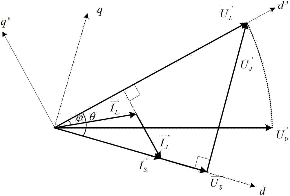
[0037] figure 2 Shown is the vector diagram of the voltage sag compensation strategy for the unified power quality controller (UPQC) with zero active power injection. in, is the system voltage vector before the sag, is the system voltage vector after the sag occurs, is the load voltage vector after compensation, Inject a voltage vector for the series side of the UPQC, is the load current vector, is the system current vector, Inject the current vector for the parallel side of the UPQC. Such as figure 2 As shown, when a voltage sag occurs in the system, the UPQC series part injects into the system a compensation voltage vector that is ahead and perpendicular to the system voltage vector. At the same ti...


PUM


Abstract

The invention belongs to the technical field of unified power quality conditioner voltage dip compensation control, and discloses a voltage dip compensation method of unified power quality conditioner with zero input active power. Zero input active power injection voltage dip (swell) compensation is achieved through the method of coordinately controlling output voltage of a cascade current converter of the unified power quality conditioner and output current of a multiple current converter. The compensation control method is simple and feasible, voltage dip (swell) persistent and continuous compensation of a device is achieved, and reliability of device compensation is improved. The problem that the direct voltage is in an undervoltage state or in an overvoltage state brought by active power injection in a compensation process is avoided, a resume or restart process of a compensation rear device is not needed, and stability of the device is improved.

Description

technical field [0001] The invention belongs to the technical field of voltage sag (swell) compensation control for a unified power quality regulator, and in particular relates to a voltage sag (swell) compensation method for a unified power quality regulator with zero active power injection. Background technique [0002] The sensitivity of modern industrial, commercial and residential electrical equipment, such as high-performance office equipment, precision experimental instruments, frequency conversion speed control equipment, programmable logic controllers, various automatic production lines, and computer systems, to changes in power supply characteristics is increasing year by year. ; At the same time, power quality problems are becoming more and more complex, and losses caused by power quality disturbances are increasing day by day. Therefore, in order to improve the quality of power supply, reduce the losses caused to users due to power quality problems, protect the i...

Claims


Application Information

Patent Timeline
Patent Type & Authority Applications(China)
IPC IPC(8): H02J3/12H02J3/18
CPCY02E40/30
Inventor 徐云飞肖湘宁徐永海龙云波于宝来
Owner NORTH CHINA ELECTRIC POWER UNIV (BAODING)
Why Eureka
Try Eureka