Motor stator coil winding machine

A technology of motor stator and winding machine, applied in the field of motor stator coil winding machine

Inactive Publication Date: 2013-07-10
JIANGSU UNIV OF TECH
View PDF3 Cites 32 Cited by
  • Summary
  • Abstract
  • Description
  • Claims
  • Application Information

AI Technical Summary

Problems solved by technology

The above-mentioned utility model needs two motors and can only solve the winding problem of narrow slots

Method used


Image

  • Motor stator coil winding machine
  • Motor stator coil winding machine

Examples


Embodiment 1

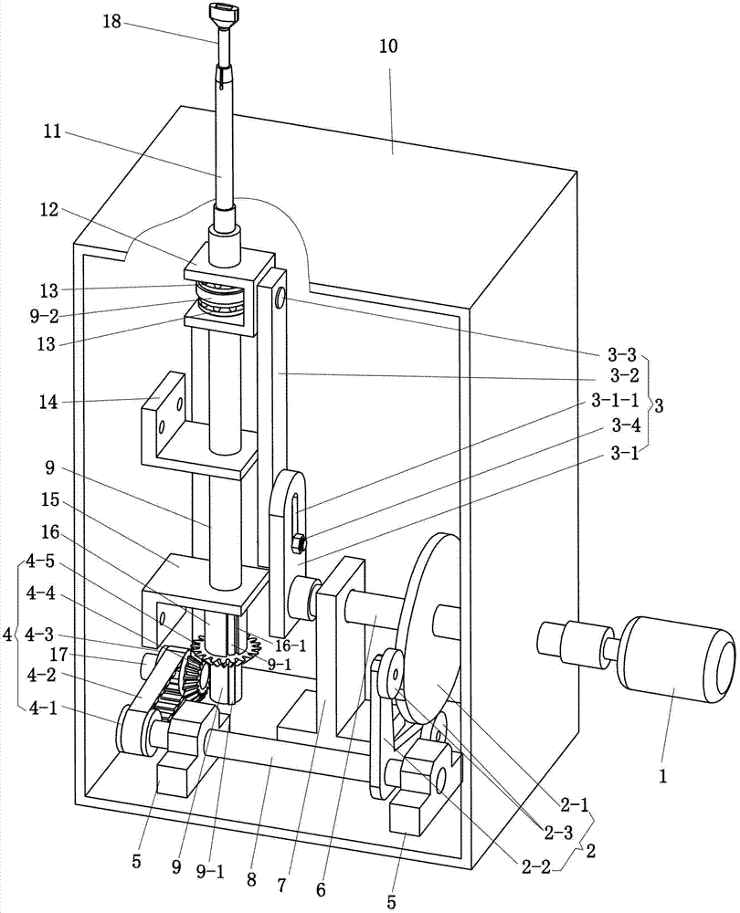
[0024] See figure 1 , The motor stator coil winding machine includes a casing 10, a drive motor 1, a power shaft 6, a main shaft 9, a long transmission shaft 8, and a short transmission shaft 17.

[0025] A support 7 and two supports 5 are fixed on the bottom plate of the box body 10, the power shaft 6 is supported by the side plate of the support 7 and the box body 10, and the transmission long axis 8 is supported by the two supports 5. An upper mount 14 and a lower mount 15 are fixed on the other side plate.

[0026] The cam mechanism 2 has a cam 2-1 fixed on the power shaft 6, an angular swing frame 2-2 fixed on the transmission long shaft 8, and rollers 2-3 are respectively hinged on the two ends of the swing frame 2-2. , The roller 2-3 rolls along the outer peripheral surface of the cam 2-1.

[0027] The middle part of the main shaft 9 is in the guide holes of the upper and lower mounts 14, 15, the main shaft 9 extends upwards through the guide holes of the casing 10, a...


PUM


Abstract

A motor stator coil winding machine comprises a box body, a driving motor, a power shaft and a main shaft, wherein a support frame and two support seats are fixed on a bottom board of the box body, the power shaft is supported by the support frame and the box body, the two support seats support a transmission long shaft, an upper installation seat and a lower installation seat are fixed on the box body, the middle portion of the main shaft is located in guide holes of the upper installation seat and the lower installation seat, a winding shaft is arranged at one end, extending upwards out of the box body, of the main shaft, a bushing is arranged at a position, extending downwards out of the lower installation seat, of the main shaft, the main shaft, the upper installation seat, the lower installation seat and the bushing are all in movable connection, the power shaft is driven by the driving motor and drives the transmission long shaft to rotate in positive and negative directions through a cam mechanism, the transmission long shaft drives the main shaft to rotate in positive and negative directions through a transmission mechanism with a bevel gear pair, a driven bevel gear is connected at the position, located below the bushing, of the main shaft, a connector is arranged at the upper portion of the main shaft, and a crank connection rod mechanism driving the main shaft to make linear motion back and forth is arranged between a power head and the connector. The motor stator coil winding machine can achieve narrow-notch and large-angle winding in a rotary mode.

Description

[0001] A motor stator coil winding machine, including a box body, a driving motor, a power shaft and a main shaft, a bracket and two supports are fixed on the bottom plate of the box body, the power shaft is supported by the bracket and the box body, and the two supports support a transmission The long axis is fixed on the box with an upper mounting seat and a lower mounting seat. The middle part of the main shaft is in the guide hole of the upper and lower mounting seats. There is a winding shaft on the end of the main shaft protruding upward from the box, and the main shaft protrudes downward. There is a bushing on the lower mounting seat, the main shaft and the upper mounting seat, the lower mounting seat, and the bushing are all dynamically connected. The power shaft is driven by the drive motor and drives the long transmission shaft to rotate positively and negatively through the cam mechanism. The long transmission shaft passes through the The transmission mechanism with a ...

Claims


Application Information

Patent Timeline
Patent Type & Authority Applications(China)
IPC IPC(8): H02K15/04H02K15/085
Inventor 孙奎洲
Owner JIANGSU UNIV OF TECH
Why Eureka
Try Eureka