
Apparatus and method for producing packaging

A packaging and composite packaging technology, applied in the field of manufacturing packaging, can solve the problems of reducing process efficiency and increasing steps

Active Publication Date: 2013-07-10
SIG TECH AG
View PDF6 Cites 24 Cited by
  • Summary
  • Abstract
  • Description
  • Claims
  • Application Information

AI Technical Summary

Problems solved by technology

This increases the number of steps in the process, thereby reducing process efficiency

Method used


Image

  • Apparatus and method for producing packaging
  • Apparatus and method for producing packaging
  • Apparatus and method for producing packaging

Examples


Embodiment Construction

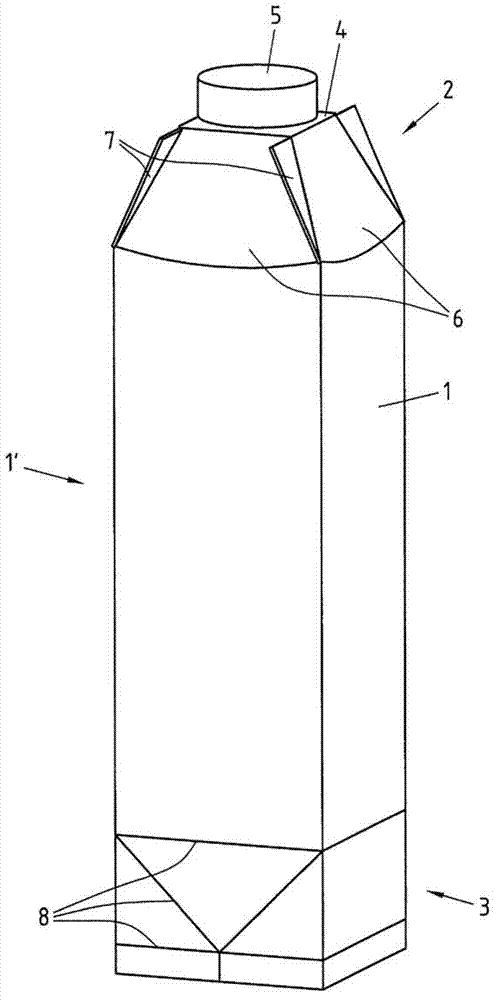
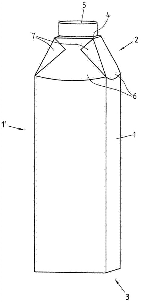
[0048] figure 1 A package 1', closed on one side, manufactured from the casing 1 is shown. The housing 1 has a gable area 2 and a bottom area 3 at its two ends. The package 1' has a square cross-section. The casing 1 is folded regularly from the blank, wherein two edges are joined together to form a tube. While the bottom area 3 remains open, the gable area 2 is closed. so, figure 1 The package 1' shown represents an intermediate stage of the manufacturing process in which the package 1' is first formed from the shell 1 open on both sides and thereafter the filled and closed (ready-for-sale) package is formed.

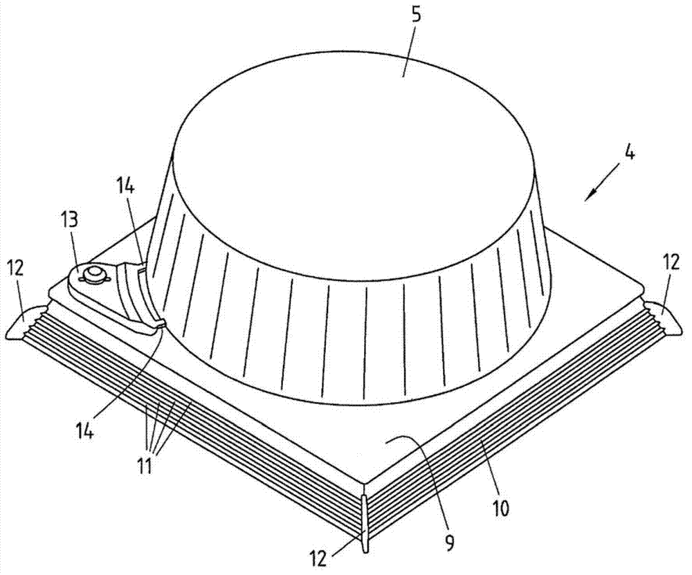
[0049] In the gable area 2 , the housing 1 is connected to a flow-guiding element 4 with a screw cap 5 . exist figure 1 In the illustrated embodiment, the gable area 2 is formed in the shape of a flat-topped pyramid. As a result, the packaging 1' has, in addition to the four gable surfaces 6 in the gable area 2, four bevels 7 protruding from the gable area 2 for...


PUM


Abstract

Illustrated and described is an apparatus for producing packaging, in particular composite packaging for liquid foodstuffs, having a cross-sectional area that decreases in the pour-out direction in the gable region, composed of a jacket (1) having a gable region (2) having a plurality of gable faces (6) and of a pour-out element (4), wherein the apparatus has at least one rotatable mandrel wheel (15) having a plurality of mandrels (17) for holding the jackets. Additionally illustrated and described are a method for producing such packaging and a gable press for use with the abovementioned apparatus. In order to allow easier and more cost-effective production, it is proposed that the apparatus has a gable press (28), assigned to a single mandrel-wheel position, for folding the gable region, in order to connect all of the gable faces of the gable region of the jacket to the pour-out element and to seal the protruding ears (7) in the same mandrel-wheel position.

Description

technical field [0001] The invention relates to a device for producing a package, in particular a composite package for liquid food, with a cross-section that decreases in the direction of flow in the gable area, the package being composed of an outer shell with a gable area and The gable area has a plurality of gable faces, wherein the device has at least one rotatable mandrel wheel, the mandrel wheel has a plurality of mandrels for receiving the housing, and for manufacturing the mandrel A method for packaging, the method may further comprise the steps of: [0002] a) Push the guide part onto the mandrel of the mandrel wheel, [0003] b) Push the housing onto the mandrel of the mandrel wheel, [0004] c) Fold the entire gable face of the gable area of ​​the shell and connect the gable face to the [0005] deflector parts, [0006] d) seal protruding roll corners, [0007] e) Flip and glue the rolled corners, [0008] f) Remove the package from the mandrel. [0009] Fu...

Claims


Application Information

Patent Timeline
IPC IPC(8): B31B1/00B65B3/02B65B61/18
CPCB65B3/027B65B51/10B65B55/04B31B50/84B31B2100/00B31B50/024B31B50/322B31B50/649B31B2110/35B31B2100/0022B65B3/02B65B7/2835B65B55/10
Inventor 克里斯托夫·肯拉尔夫·德里森托马斯·费滕米夏埃尔·海尔
Owner SIG TECH AG
Learn More