Flue-gas cleaner

A purifier and flue gas technology, applied in chemical instruments and methods, dispersed particle separation, combined devices, etc., can solve the problems of small processing area, short flue gas flow, single processing object, etc., and achieve large processing area and purification effect. Good, good oxidation effect

Inactive Publication Date: 2013-07-17
周勇定
View PDF7 Cites 24 Cited by
  • Summary
  • Abstract
  • Description
  • Claims
  • Application Information

AI Technical Summary

Problems solved by technology

[0011] The present invention aims to solve the problems of short flue gas flow, small treatment area and single treatment object in the prior art, and aims to provide a long flue gas flow, large treatment area, and comprehensive treatment of various toxic and harmful gases. flue gas purifier

Method used


Image

  • Flue-gas cleaner
  • Flue-gas cleaner
  • Flue-gas cleaner

Examples


Embodiment Construction

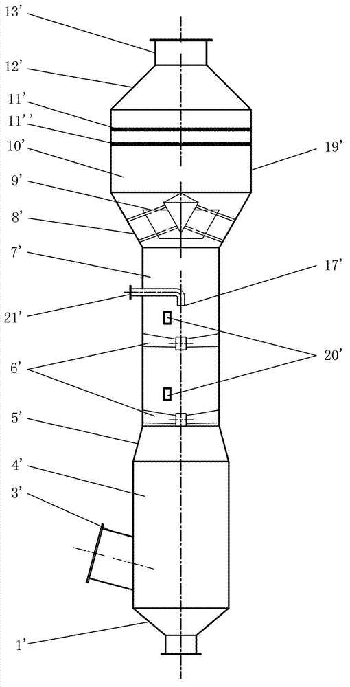
[0036] refer to figure 1 , an existing desulfurization tower, its defects have been described above, and will not be repeated here.

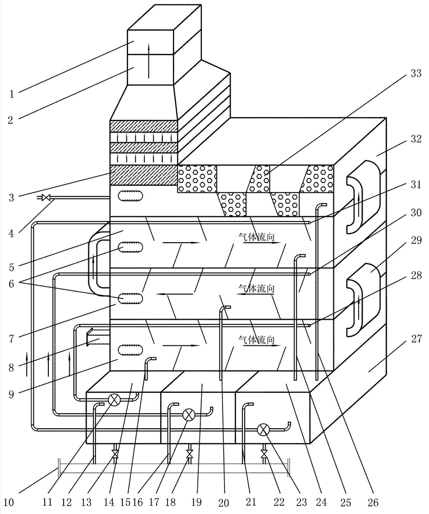
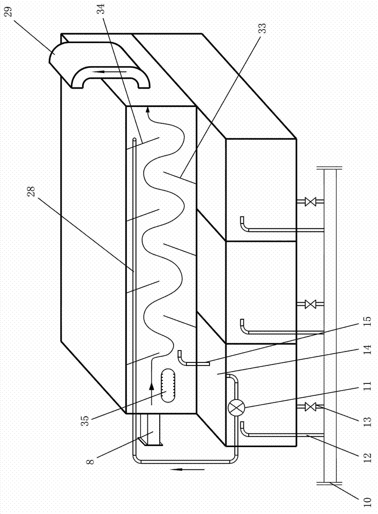
[0037] refer to figure 2 , a flue gas purifier of the present invention, comprising liquid storage tank 27, water mist chamber 9, lye spray chamber 7, oxidation spray chamber 5, gas-liquid separation chamber 32, activated carbon The adsorption chamber 3 and the purified gas outlet 1, the liquid storage tank 27 is at least divided into the first sub-slot 14, the second sub-slot 19 and the third sub-slot 25, and each sub-slot passes through the sewage branch pipes 13, 18, 22 respectively Connected to the sewage main pipe 10; the water mist chamber 9, the lye spray chamber 7, the oxidation spray chamber 5 and the gas-liquid separation chamber 32 are connected from end to end through the flue gas pipe 29 in order to form a horizontal reciprocating series channel; the water One end of the mist chamber 9 is provided with a flue gas inlet pipe 8, an...


PUM


Abstract

The invention discloses a flue-gas cleaner, comprising a liquid storage tank, a water spray chamber, an alkali liquor spraying chamber, an oxidized spraying chamber, a gas-liquid separating chamber, an active carbon adsorption chamber and a purified gas outlet, wherein the liquid storage tank is partitioned into at least three sub-tanks; each sub-tank is respectively connected to a sewage master pipe through a sewage branch pipe; the water spray chamber, the alkali liquor spraying chamber, the oxidized spraying chamber and the gas-liquid separating chamber are orderly communicated end to end through a flue-gas pipe, so as to form transverse channels which are connected in series in a reciprocating manner; the inner top part of each chamber is provided with the spraying pipe; and the side is communicated with corresponding sub-tank through a drain tube. The flue-gas cleaner is long in flue-gas flow, large in processing area, high in efficiency, and wide in adaptability, and can comprehensively process various toxic and harmful gases.

Description

technical field [0001] The invention relates to the field of flue gas purifiers, in particular to a device for treating toxic and harmful flue gas generated during the preparation and operation of biodiesel, oil refining, smelting, rubber production, incinerators, and industrial boilers. It is suitable for chemical, light Industrial, rubber, machinery, shipbuilding, automobile, petroleum and other industries. Background technique [0002] With the continuous development of modern industry, more and more attention is paid to the control of industrial pollution. Common industrial pollution includes waste gas, waste water and waste residue. Such as combustion in industrial boilers, the SO produced during the combustion process 2 Such harmful substances, if discharged into the atmosphere without strict and effective desulfurization, will irritate the human respiratory tract, and will cause toxic and side effects to the whole body after being inhaled into the blood, and even in...

Claims


Application Information

Patent Timeline
Patent Type & Authority Applications(China)
IPC IPC(8): B01D53/75B01D53/72B01D53/50B01D53/48B01D50/00
Inventor 周勇定
Owner 周勇定
Why Eureka
Try Eureka