Object stage with accurately-controlled position

A technology of precise control and stage, which is applied in the field of stage, can solve the problem that the stage is not easy to be positioned accurately, and achieve the effect of not being easy to move and high stability

Inactive Publication Date: 2013-07-17
KUN SHAN POWER STENCIL
View PDF10 Cites 4 Cited by
  • Summary
  • Abstract
  • Description
  • Claims
  • Application Information

AI Technical Summary

Problems solved by technology

[0009] The technical problem to be solved by the present invention is the problem that the object stage in the prior art is not easy to be positioned accurately, and a new object stage with precise position control is provided, which has the advantages of stable support and accurate positioning

Method used


Image

  • Object stage with accurately-controlled position
  • Object stage with accurately-controlled position
  • Object stage with accurately-controlled position

Examples


Embodiment 1

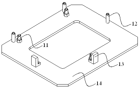
[0032] A stage with precisely controlled position, such as figure 1 As shown, it includes a support column 11, a pin 12, a plunger 13 and a base 14 for fixing the support column 11, the pin 12, and the plunger 13. The support column 11 of the object stage has a height adjustment function, through which the levelness of objects placed on the object stage can be adjusted. The pin 12 is an eccentric pin, and the position of the object can be adjusted to a certain extent on the horizontal plane by its rotation.

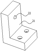
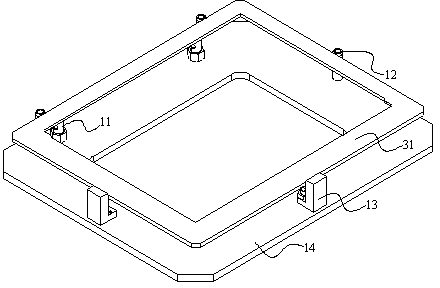
[0033] figure 2 Shown is a schematic diagram of the structure of the plunger on the abutment in this embodiment, which consists of a circular ball head 21 and a base 22 to form the exterior, and the circular ball head is lifted by the spring inside the base. image 3 It is a schematic diagram of loading on the stage. The stage provides a certain pressure on the object 31 through the plunger 13, so that the edge of the object to be carried can be close to the pin on the...

Embodiment 2

[0037] An object stage with precise position control, which includes an object stage and three pins for controlling the position of the object to be carried, the pins have an adjustment function, and can precisely locate the object to be carried at a certain position on the plane effect. The pin with adjustment function is an eccentric pin, which is composed of two cylinders with different axes. The surface of the two cylinders has a thread structure, and the eccentric pin is fixed on the stage through this structure, and is used for the locknut The adjusted pin is fixed on the stage, and an adjustment mechanism is provided on the pin. In this embodiment, the adjustment mechanism is a circular hole, which can be rotated and adjusted by inserting a bar rod.

[0038] The stage in this embodiment has three hard-point support columns, which can fix the object to be carried on a certain plane through three support points, and the height of the hard-point support columns is adjustab...

Embodiment 3

[0042] An object stage with precise position control is used for placing objects with regular shape and high position accuracy requirements. The support frame includes support columns, pins and abutments for fixing the support columns and the pins. The support columns are three hard support columns whose positions are not on a straight line, which are made of stainless steel, and have a threaded structure that can rotate the support column at the position where the support column contacts the abutment, that is, it can be adjusted through the thread structure The height of each support column support point. 3 support columns can fix the supported table on a certain plane. In this embodiment, three eccentric pins are fixed on the abutment, which are made of hard and wear-resistant materials. The position of the pins is on the periphery of the triangle formed by the support columns, and they are not on a straight line. Depending on the shape and size of the supported object. Th...


PUM


Abstract

The invention relates to an object stage with an accurately-controlled position, which is mainly used for solving the problem that an object stage cannot be accurately positioned in the prior art. The object stage with an accurately-controlled position comprises support columns, pins, a base and plungers, wherein the support columns and the pins are fixed on the base; the pins which are vertical to the base are higher than the support columns; a plane is formed by the apexes of support positions on the support columns; the support positions of the support columns have curved structures or conical structures; and supported objects are arranged at the support positions of the support columns, and are positioned on the inner sides of the pins and the plungers. According to the object stage, the problem is well solved; and the object stage can be applied to industrial production of precisely-operated object stages.

Description

technical field [0001] The invention relates to an object carrier with precise position control. Background technique [0002] With the development of society, various industries have higher and higher requirements for the placement environment and bearing platform of the hardware facilities involved in the industry, especially for the placement of some precision instruments. For example, in the operation table involving the work of optical components, it is often required that the supporting platform has sufficient stability. [0003] Chinese patent CN101738127A discloses a heat-insulating support device, which includes a cold platform with multiple mounting holes and a support rod for supporting the cold platform, and the support rod includes an upper support rod and a lower support rod. Cooperate with the mounting holes in a point contact or line contact manner respectively, but the support frame of the invention has four support columns. [0004] Chinese patent CN25745...

Claims


Application Information

Patent Timeline
Patent Type & Authority Applications(China)
IPC IPC(8): B25H1/00
Inventor 魏志凌高小平程晔
Owner KUN SHAN POWER STENCIL
Why Eureka
Try Eureka