

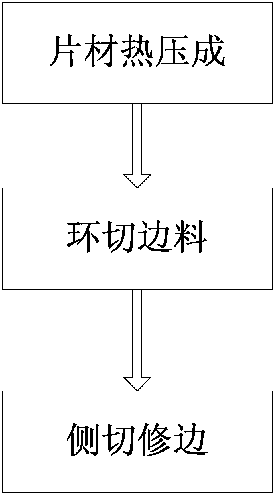
Three-dimensional side cutting method and die for stereoscopic high stretch formed film
A technology of stretch forming and mould, which is applied in the field of film cutting method and mould, can solve the problem that the film cannot be cut into two-dimensional planes, etc., and achieve the effect of expanding the application field of decoration technology, improving product efficiency, and reducing defective products
- Summary
- Abstract
- Description
- Claims
- Application Information
AI Technical Summary
Problems solved by technology
Method used
Image

Examples
Embodiment Construction
[0045] In order to have a clearer understanding of the technical features, purposes and effects of the present invention, the specific implementation manners of the present invention will now be described in detail with reference to the accompanying drawings.
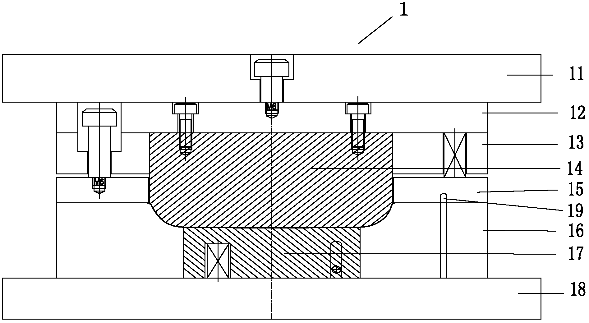
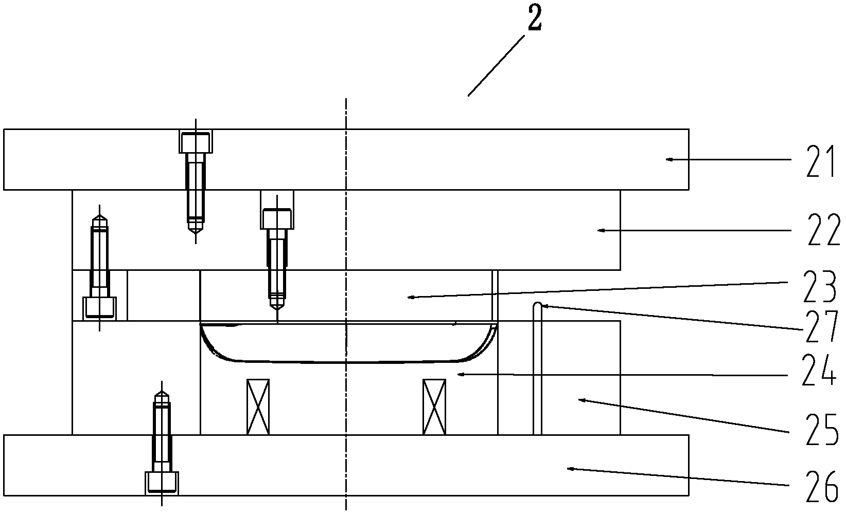
[0046] Such as Figure 1-Figure 8 As shown, the number labels in the figure represent:
[0047] 1-Thermocompression forming mold, 11-the first panel, 12-the fixed plate of the upper mold, 13-the first upper template, 14-the first punch, 15-pressing plate, 16-the first lower template, 17-the first bomb Block, 18-the first base plate, 19-the first positioning column;
[0048] 2-ring cutting die, 21-second panel, 22-second upper template, 23-second punch, 24-second bullet, 25-second lower template, 26-second bottom plate, 27-second positioning post;
[0049] 3-side cutting die, 31-the third panel, 32-the third upper template, 33-briquetting block, 34-the third punch, 351a-the first oil cylinder, 351b-the first row of kn...
PUM
| Property | Measurement | Unit |
|---|---|---|
| thickness | aaaaa | aaaaa |
| thickness | aaaaa | aaaaa |
| thickness | aaaaa | aaaaa |
Abstract
Description
Claims
Application Information