Appearance inspection apparatus of workpiece and appearance inspection method of workpiece
A technology for visual inspection devices and workpieces, which is applied to furnace components, metal processing, conveyor objects, etc., can solve problems such as decreased shooting accuracy, decreased electrostatic adsorption force, and electrostatic destruction characteristics of workpieces, and achieves improved shooting accuracy and improved processing capabilities. , Eliminate the effect of electrostatic destruction and/or characteristic deterioration
- Summary
- Abstract
- Description
- Claims
- Application Information
AI Technical Summary
Problems solved by technology
Method used
Image

Examples
no. 1 approach
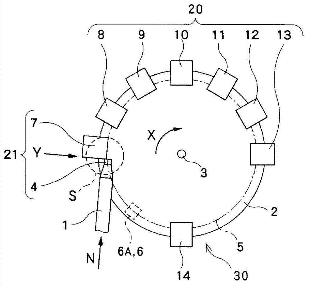
[0054] Embodiments of the present invention will be described below with reference to the drawings. Figure 1 to Figure 9 It is a figure which shows the 1st Embodiment of the appearance inspection apparatus of the workpiece|work according to this invention, and the appearance inspection method of a workpiece.
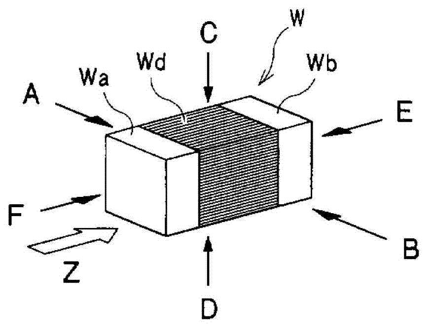
[0055] First, through figure 2 The workpiece inspected by the workpiece visual inspection device will be described.
[0056] exist figure 2 Among them, the workpiece W, which becomes a chip component such as capacitors and / or resistors, has a hexahedron shape and has a main body Wd made of an insulator and electrodes Wa, Wb made of conductors formed at both ends of the main body Wd in the longitudinal direction. In the case of performing the visual inspection of the workpiece W, the workpiece W is placed on the transfer table 2 described later, and the transfer table 2 is moved to figure 2 Rotate in the direction of the arrow Z to transport the workpiece W. And, ...
no. 2 approach
[0113] Next, use Figure 10 to Figure 15 A second embodiment of the present invention will be described.
[0114] Figure 10 to Figure 15 The second embodiment of the present invention shown is only different in that a conductive plate (conductor) 15 is arranged under the conveying table 2 instead of arranging the charging unit 6A under the conveying table 2, and the other structures are the same as Figure 1 to Figure 9 The first embodiment shown is substantially the same.
[0115] exist Figure 10 to Figure 15 In the second embodiment shown, for the Figure 1 to Figure 9 The parts that are the same as those in the first embodiment shown are given the same symbols, and detailed description thereof will be omitted.
[0116] here, Figure 10 is viewed from the direction of the arrow Y at figure 1 A perspective view of the region S enclosed by the dashed line in , with Figure 4 Corresponding. exist Figure 10 On the lower side of the middle conveying platform 2, the co...
PUM
 Abstract
Description
Claims
Application Information