Anti-overturning bridge pier supporting mechanism

An anti-overturning and bridge pier technology, which is applied to bridges, bridge parts, bridge construction, etc., can solve problems such as support seat emptying and overturning accidents, and achieve the effects of preventing overturning, improving the stress state, and shortening the construction time

Inactive Publication Date: 2013-07-17
NORTHEAST FORESTRY UNIVERSITY
View PDF10 Cites 13 Cited by
  • Summary
  • Abstract
  • Description
  • Claims
  • Application Information

AI Technical Summary

Problems solved by technology

[0003] In order to solve the problem in the prior art that the single-point support of single-pillar pier bridges is likely to cause the support seat to fall out of the air, or even overturn accidents, the invention further provides a bridge anti-overturning pier support mechanism

Method used


Image

  • Anti-overturning bridge pier supporting mechanism
  • Anti-overturning bridge pier supporting mechanism

Examples


specific Embodiment approach 1

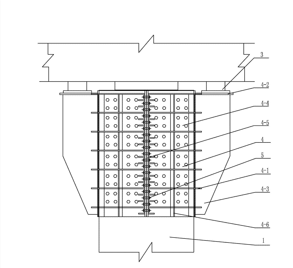
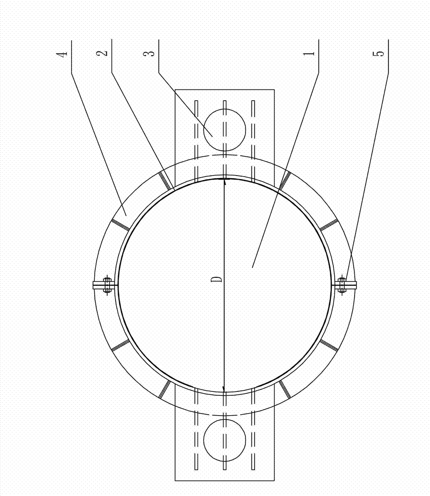
[0007] Specific implementation mode one: combine Figure 1-Figure 2 Describe the support mechanism of a bridge anti-overturning pier in this embodiment. The support mechanism includes a pier column 1, the support mechanism also includes a carbon fiber cloth 2, a steel hoop assembly 4 and two supports 3, and the steel hoop assembly 4 includes Two horizontal support plates 4-2, two semicircular cylinders 4-4 and four connecting pieces 4-5; two semicircular cylinders 4-4 form a circular cylinder through four connecting pieces 4-5 The upper surface of each horizontal support plate 4-2 is respectively provided with a support 3, and the two horizontal support plates 4-2 are horizontally arranged on the upper surface of the circular cylinder in a straight line, and the carbon fiber cloth 2 is wound on the top of the pier 1, and the circular cylinder is set on the carbon fiber cloth 2 on the outside of the pier 1.

specific Embodiment approach 2

[0008] Specific implementation mode two: combination Figure 1-Figure 2 To illustrate a support mechanism for bridge anti-overturning piers in this embodiment, the steel hoop assembly 4 also includes a plurality of semicircular ribs 4-1 and a plurality of rectangular ribs 4-6; every two semicircular ribs 4-1 forms a circular rib, a plurality of circular ribs are uniformly set on the outer wall of the circular cylinder, and a plurality of rectangular ribs 4-6 are uniformly arranged on the circular cylinder On the outer wall of the body, and the center line of each rectangular rib plate 4-6 along the length direction coincides with the axial center line of the circular cylinder, the other is the same as the first embodiment.

specific Embodiment approach 3

[0009] Specific implementation mode three: combination Figure 1-Figure 2 To illustrate a support mechanism for a bridge anti-overturning pier in this embodiment, the steel hoop assembly 4 also includes a plurality of support ribs 4-3, and the plurality of support ribs 4-3 are uniformly arranged on the circular cylinder On the outer wall, the upper end of each supporting rib 4-3 is connected to the lower surface of the corresponding horizontal supporting plate 4-2, and the other is the same as the first embodiment.


PUM


Abstract

The invention relates to an anti-overturning bridge pier supporting mechanism, in order to solves the problem that a single-column pier bridge easily causes disconnection of a supporting seat and even capsizing cases as adopting a single-point supporting beam in the prior art. The supporting mechanism comprises a pier column, carbon fiber cloth, a steel hoop component and two supporting seats, the steel hoop component comprises two horizontal support plates, two semicircular cylinders and four connectors, the two semicircular cylinders form a circular cylinder through the four connectors, one supporting seat is arranged on the upper surface of each horizontal support plate, the two horizontal support plates are arranged on the upper surface of the circular barrel horizontally and linearly, the carbon fiber cloth is wound at the top end of the pier column, and the circular cylinder is sleeved on the carbon fiber cloth on the outer side of the pier column. The anti-overturning bridge pier supporting mechanism is used in the field of bridge reinforcing.

Description

technical field [0001] The invention relates to a support mechanism for a bridge anti-overturning pier. Background technique [0002] In recent years, continuous girder bridges with single-column piers have been widely used as urban overpasses and viaducts, because of their simple and smooth shape, small building height, good visibility under the bridge, adaptable to many occasions, convenient construction and low engineering cost, etc. And has been greatly developed. However, since the single column pier bridge is supported by a single support seat in the transverse bridge direction, the overall lateral instability may occur under the eccentric load of the lane. In recent years, many overturning accidents have occurred, causing major economic losses and adverse social impacts . Accident investigation conclusions are mostly caused by overloading and overrunning of vehicles. The overturning and collapse of bridge structures occurs under the action of extreme events, which ...

Claims


Application Information

Patent Timeline
Patent Type & Authority Applications(China)
IPC IPC(8): E01D19/04
Inventor 孙全胜宋金良高红帅
Owner NORTHEAST FORESTRY UNIVERSITY
Why Eureka
Try Eureka