Sludge-type soil combined secondary dike-back pressure diking method

A technology of silt and sub-dykes, applied in construction, water conservancy projects, marine engineering and other directions, can solve the problems of increasing the cost of dam projects, restricting the construction progress of dam projects, and rising unit prices, and achieves high construction efficiency, fast construction speed, and construction cost. low effect

Inactive Publication Date: 2013-07-17
SHANGHAI WATERWAY ENG DESIGN & CONSULTING CO LTD
View PDF3 Cites 7 Cited by
  • Summary
  • Abstract
  • Description
  • Claims
  • Application Information

AI Technical Summary

Problems solved by technology

Now soil, sand, and stone resources are becoming more and more scarce, the supply is becoming increasingly tight, and the unit price is also rising, which not only greatly increases the cost of the dam project, but also seriously restricts the construction progress of the dam project

Method used


Image

  • Sludge-type soil combined secondary dike-back pressure diking method
  • Sludge-type soil combined secondary dike-back pressure diking method
  • Sludge-type soil combined secondary dike-back pressure diking method

Examples


Embodiment 1

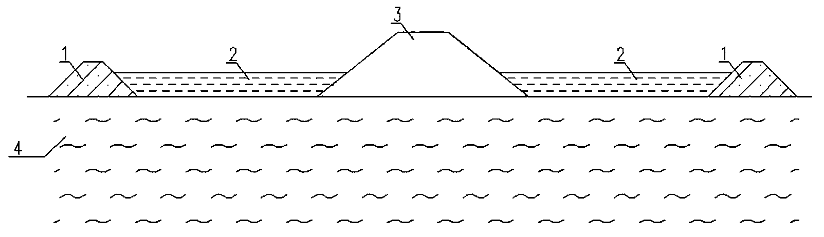
[0017] Embodiment 1, the embankment method of silty soil on both sides combined with sub-dike back pressure:

[0018] see figure 1 , sub-dikes 1 are arranged on both sides inside and outside the main dike 3 of the dam, and the distance between the main dike 3 and the sub-dikes 1 is generally 3 to 6 times the height of the main dike 3 . Between the main embankment 3 and the sub-dike 1, set up the silt soil counterpressure embankment core 2, whose top elevation does not exceed the top elevation of the sub-dike 1, and the sub-dike 1 top elevation is generally higher than the silt soil backpressure embankment core 2 top elevation 0~0.5m. The heights of the sub-dike 1 and the silty soil counterpressure embankment core 2 are generally not less than 1 / 3 of the height of the main dike 3 and not greater than 2 / 3 of the height of the main dike 3 . The silty soil backpressure embankment core is formed by dredging or backfilling, and the sub-dike 1 and the silty soil backpressure embank...

Embodiment 2

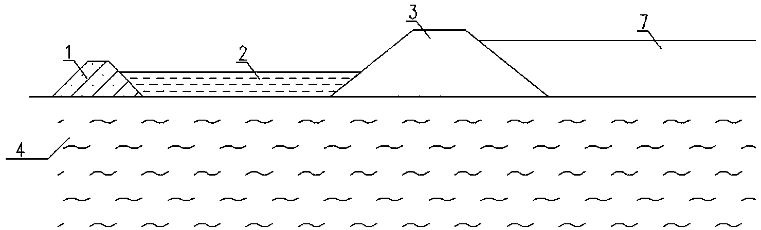
[0021] Embodiment two, the embankment method of one side silty soil combined sub-dike back pressure:

[0022] see figure 2 , a sub-dyke 1 of a certain height is set at a certain distance on one side of the main dyke 3 of the dam, and a silty soil backpressure embankment core 2, sub-dyke 1 and silty soil backpressure dyke are set between the main dyke 3 and the sub-dyke 1 The core 2 is combined to form a back pressure structure, which forms a back pressure on one side of the main embankment 3. On the other side of the main dike 3 of the dam, the dredging fill 7 is used as a back pressure structure to form a back pressure on the other side of the main dike 3 . All the other are the same as embodiment one.

Embodiment 3

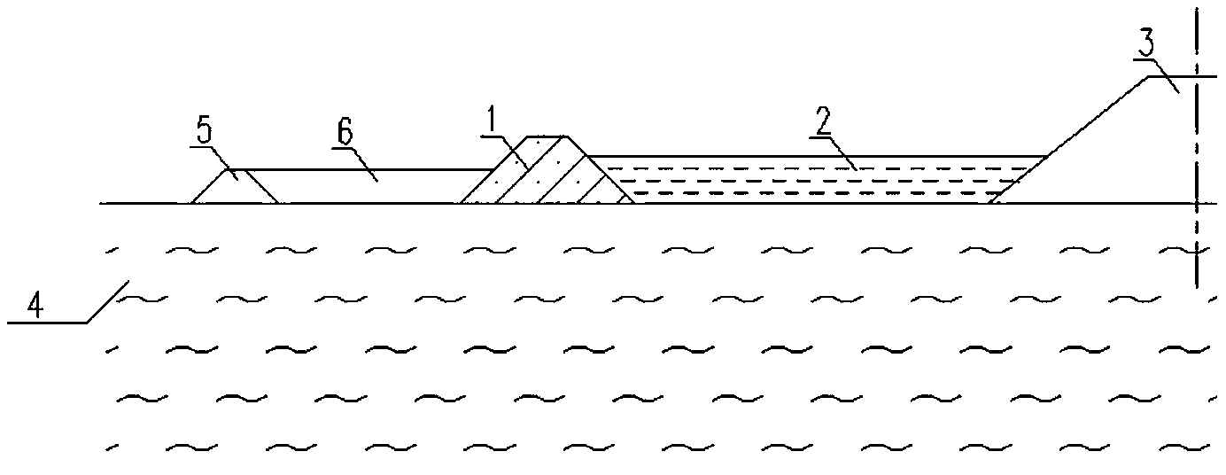
[0023] Embodiment three, the embankment method of two-stage silty soil combined with two-stage sub-dyke back pressure:

[0024] see image 3 , when the height of the main embankment 3 is relatively high or the soft soil foundation 4 is very weak, the two-stage backpressure structure formed by combining the two-stage sub-dike and the two-stage silt soil backpressure embankment core is used to improve the stability of the main embankment 3: in the sub-dike A second-level sub-dike 5 is set at a certain distance from the back main dike 3 side of the dike 1, and a second-level silty soil backpressure dike core 6 is set between the sub-dike 1 and the second-level sub-dike 5, and the second-level sub-dike 5 and the second-level backpressure structure formed by the combination of the second-level silty soil backpressure embankment core 6, thereby forming a two-level backpressure structure formed by the combination of two-level sub-dikes and two-level silt soil backpressure embankment ...


PUM


Abstract

The invention relates to a diking method of a soft soil foundation dike, particularly a sludge-type soil combined secondary dike-back pressure diking method. The technical scheme of the invention is that a secondary dike is arranged on one or two sides inside and outside a main dike of a dike, the distance between the main and secondary dikes is 3-6 times height of the main dike, the section of the secondary is trapezoid or triangular, the height of the top of the secondary dike is higher than that of the top of a sludge-type soil-back pressure dike core by 0-0.5m, the sludge-type soil-back pressure dike core is arranged between the main and secondary dikes and is formed by hydraulic reclamation or backfilling, the heights of the secondary dike and the sludge-type soil-back pressure dike core are not smaller than one third and not larger than two third of the height of the main dike, and the secondary dike and the sludge-type soil-back pressure dike center are combined to form the back pressure structure. The diking method is suitable for the soft soil foundation dike projects, particularly the soft soil foundation dike projects without wave action conditions.

Description

technical field [0001] The invention relates to an embankment method for embankment engineering soft soil foundation embankment. Background technique [0002] Fill embankments and dams on soft soil foundations such as silt and silty soil, such as seawalls, seawalls, sea barriers, flood control dikes, cofferdams, cofferdams, ash reservoir dikes, reservoir dikes, approach dikes, embankments, roadbeds, and roads into the sea , revetment, etc., in order to maintain the overall stability of the dam, in addition to the soft foundation treatment, the back pressure structure is generally used on one or both sides of the inside and outside of the dam, and the weight of the back pressure structure is used to improve the stability of the dam. The back pressure structure adopts the types of filling, riprap (including mountain rock, mountain stone, dregs, pond slag, etc.), bagged sand (sand), dredging sand (sand), backfilling sand (sand), etc. A large amount of cohesive soil, silt, sand...

Claims


Application Information

Patent Timeline
Patent Type & Authority Applications(China)
IPC IPC(8): E02B3/04E02B7/00
Inventor 马兴华黄东海周海顾勇方伟陈越邹余侯海伟
Owner SHANGHAI WATERWAY ENG DESIGN & CONSULTING CO LTD
Why Eureka
Try Eureka