Structural waterproof parallel air flue type natural ventilator

A natural ventilator and waterproof technology, applied in the field of ventilators, can solve problems such as leakage into the room and easy infiltration of rainwater, and achieve the effects of improving drainage capacity, improving waterproof capacity, and reducing flow velocity

Active Publication Date: 2013-07-17
SICHUAN MCWELL TECH
View PDF7 Cites 9 Cited by
  • Summary
  • Abstract
  • Description
  • Claims
  • Application Information

AI Technical Summary

Problems solved by technology

[0004] The purpose of the present invention is to provide a structure waterproof type parallel air duct type natural ventilator, to solve the problem that the current parallel air duct type natural ventilator cannot effectively defend, dredge, collect and discharge rainwater in case of heavy rain, causing rainwater to easily infiltrate or The problem of leaking into the room

Method used


Image

  • Structural waterproof parallel air flue type natural ventilator
  • Structural waterproof parallel air flue type natural ventilator
  • Structural waterproof parallel air flue type natural ventilator

Examples


Embodiment 1

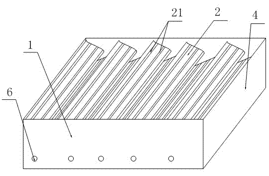
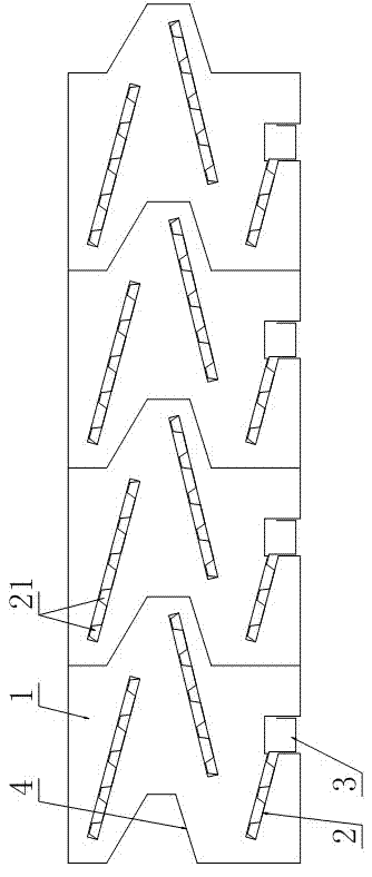
[0035] Such as figure 1 and figure 2 As shown, the special leak-proof gutter of the bowl-shaped ventilator includes a support frame 1, at least two groups of ventilation components arranged in parallel in the support frame, and an outer guard plate 4 covering the outside of the support frame, wherein each group The ventilation components are composed of at least two rainproof plates 2 arranged staggered up and down and the drainage groove 3 connected with the lowermost rainproof plate. In order to ensure the overall consistency, waterproof and reduce the difficulty of production, the drainage groove and the waterproof The rain plate adopts an integrated connection structure, that is, it is directly made into one by the processing technology of plate bending, and the bottom surface of the drainage groove is arranged horizontally, which is convenient for installation. In the same group of ventilation components, the plumb line of the lower edge of the upper flashing falls on t...

Embodiment 2

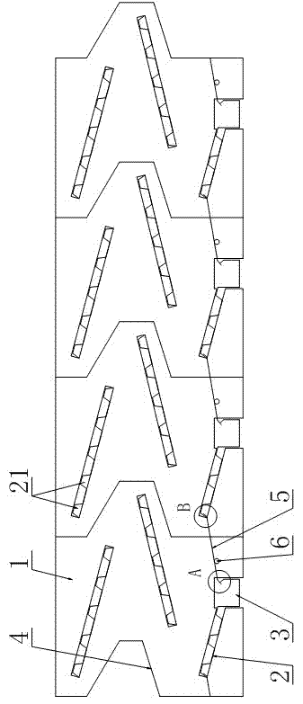
[0042] Such as image 3 As shown, the difference between this embodiment and Embodiment 1 is that, between the drainage grooves in each group of ventilation components and the lowermost rainproof plate of the adjacent group of ventilation components, there is a And adjustable opening and closing device for waterproof when closed.

[0043] Specifically, the adjustable opening and closing device includes a valve plate 5 whose one end is buckled on the lower side of the edge of the lowermost rainproof plate, and the other end is buckled on the upper part of the side wall of the gutter, and is connected with the support frame and controlled. The rotating shaft 6 that valve plate rotates. The rotation of the rotating shaft is controlled manually or electrically so as to adjust the angle of the valve plate.

[0044] In order to ensure the effective cooperation between the valve plate and adjacent components, and to facilitate the guide and collection of rainwater, the drainage gro...


PUM


Abstract

The invention discloses a structural waterproof parallel air flue type natural ventilator. The natural ventilator comprises a support framework, at least two groups of ventilation components arranged in the support framework parallelly, and an outer protective plate wrapped on the outer side of the support framework. Each group of ventilation components comprises at least two flashing boards in up-down staggered arrangement and a drainage channel connected with the lower edge of the bottom flashing board, a plurality of convex ribs in transversal arrangement and used for slowing down flowing of rainwater and guiding flow and drainage are arranged on each flashing board, and an adjustable opening and closing device is arranged on the drainage channel in each group of the ventilation components, is fastened at the edge of the bottom flashing board of the adjacent group of ventilation components, is capable of blocking and conducting indoor and outdoor air flues, and is used for waterproofing when closed. By means of simple and ingenuous improvement, rainwater can be defended, drained, collected and removed effectively, and the natural ventilator has good application effect and broad application prospect.

Description

technical field [0001] The invention relates to a ventilator, in particular to a structurally waterproof parallel air duct type natural ventilator. Background technique [0002] In some large factories, workshops or warehouses, it is often necessary to install a large-scale natural ventilation system on the roof, using the temperature difference and natural wind to discharge the overheated air, dirty air, harmful gases, etc. inside the house, usually using a roof ventilator achieve this ventilation effect. [0003] In the patents with the authorized announcement numbers CN201866883U and CN202083071U and the patent application with the application publication number CN102269460A, there are different parallel air duct type natural ventilators mainly composed of supporting frames, rainproof plates, drainage grooves and outer guard plates. . These natural ventilators solve the indoor rainproof problem of installing the roof natural ventilation system to a certain extent, but ...

Claims


Application Information

Patent Timeline
Patent Type & Authority Applications(China)
IPC IPC(8): F24F7/02F24F13/00
Inventor 梁鹏彭大林陈江喜
Owner SICHUAN MCWELL TECH
Why Eureka
Try Eureka