Objective table location method
A positioning method and stage technology, applied in the direction of measuring devices, instruments, measuring instrument components, etc., can solve the problem that the stage is not easy to be positioned accurately, and achieve the effect of not being easy to move and high stability
- Summary
- Abstract
- Description
- Claims
- Application Information
AI Technical Summary
Problems solved by technology
Method used
Image

Examples
Embodiment 1
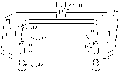
[0044] A stage with electrically controlled positions, such as figure 1 As shown, it includes a support column 11 , a pin 12 , a plunger 13 , a fixed base plate 14 and a motor 15 capable of rotating the pin 12 and the support column 11 . In the present embodiment, there are three support columns 11, and they are not on the same plane. Since the three points are fully positioned, the geometric three-point determination plane is satisfied, and the three points at the upper end of the support columns can determine the object to be carried on a plane.
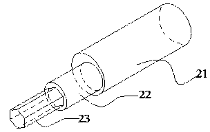
[0045] Pin 12 is an eccentric pin, such as figure 2 As shown, it consists of a part 21 that contacts the object to be carried, a part 22 fixed on the substrate 14, and a mechanism 23 whose lower end matches the electrode. The position of the object to be carried on the support column can be adjusted by the rotation of the pin.
[0046] The part of the support column 11 fixed on the base plate 14 and the lower end have a mechanism...
Embodiment 2
[0061] An electronically controlled object stage, which includes an object stage and three eccentric pins that control the position of the loaded object. The eccentric pin has an adjustment function and can precisely position the loaded object on a certain plane. role of location. The eccentric pin with adjustment function is an eccentric pin, which is composed of two cylinders with different axes. The surface of the two cylinders has a thread structure, and the eccentric pin is fixed on the stage through this structure, which is used for loosening The nut fixes the adjusted eccentric pin on the stage, and the eccentric pin is provided with an adjustment mechanism. In this embodiment, the adjustment mechanism is a circular hole, which can be rotated and adjusted by inserting a bar rod.
[0062] The stage in this embodiment has three hard-point support columns, which can fix the object to be carried on a certain plane through three support points, and the height of the hard-poi...
Embodiment 3
[0075] An electric control position stage is used to place objects with regular shape and high position accuracy requirements. The support frame includes support columns, eccentric pins and abutment for fixing the support columns and eccentric pins. The support columns are three hard support columns whose positions are not on a straight line, which are made of stainless steel, and have a threaded structure that can rotate the support column at the position where the support column contacts the abutment, that is, it can be adjusted through the thread structure The height of each support column support point. 3 support columns can fix the supported table on a certain plane. In this embodiment, three eccentric pins are fixed on the abutment, which are made of hard and wear-resistant materials. The position of the eccentric pins is on the periphery of the triangle formed by the support columns, and they are not on a straight line. Their fixed positions are corresponding to the sta...
PUM
 Abstract
Description
Claims
Application Information
 - Generate Ideas
- Intellectual Property
- Life Sciences
- Materials
- Tech Scout
- Unparalleled Data Quality
- Higher Quality Content
- 60% Fewer Hallucinations
Browse by: Latest US Patents, China's latest patents, Technical Efficacy Thesaurus, Application Domain, Technology Topic, Popular Technical Reports.
© 2025 PatSnap. All rights reserved.Legal|Privacy policy|Modern Slavery Act Transparency Statement|Sitemap|About US| Contact US: help@patsnap.com