Light guide plate and manufacture method thereof

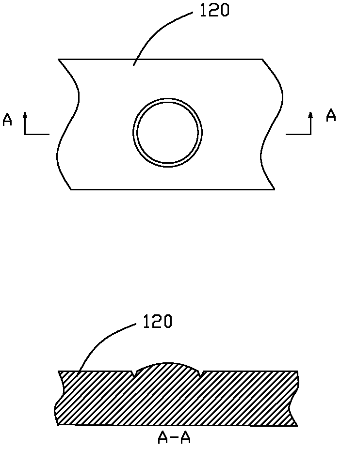
A technology of light guide plate and substrate, applied in the directions of light guide, optics, optical components, etc., can solve the problems of low light output efficiency of the light guide plate 120, low brightness of the light guide plate 120, poor light output uniformity, etc.

Active Publication Date: 2013-07-17
YANGXIN TECH SUZHOU
View PDF5 Cites 7 Cited by
  • Summary
  • Abstract
  • Description
  • Claims
  • Application Information

AI Technical Summary

Problems solved by technology

The dots 111 on the mold core 110 are generally semicircular, and semicircular dots opposite to the dots 111 on the mold core 110 will be formed on the light guide plate 120. The semicircular dots have a small reflection area and cause the light guide plate to The light extraction efficiency of 120 is low, so the light guide plate 120 with semicircular dots has low brightness and poor light uniformity

Method used


Image

  • Light guide plate and manufacture method thereof
  • Light guide plate and manufacture method thereof
  • Light guide plate and manufacture method thereof

Examples


Embodiment 1

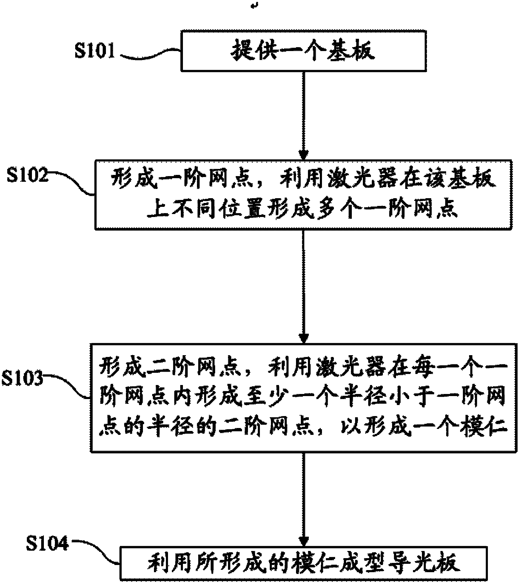
[0030] Please refer to Figure 3-5 , in this embodiment, the method for manufacturing light guide plate comprises the following steps:

[0031] In step S101 , a substrate 210 is provided first, and the substrate 210 is made of metal, preferably steel.

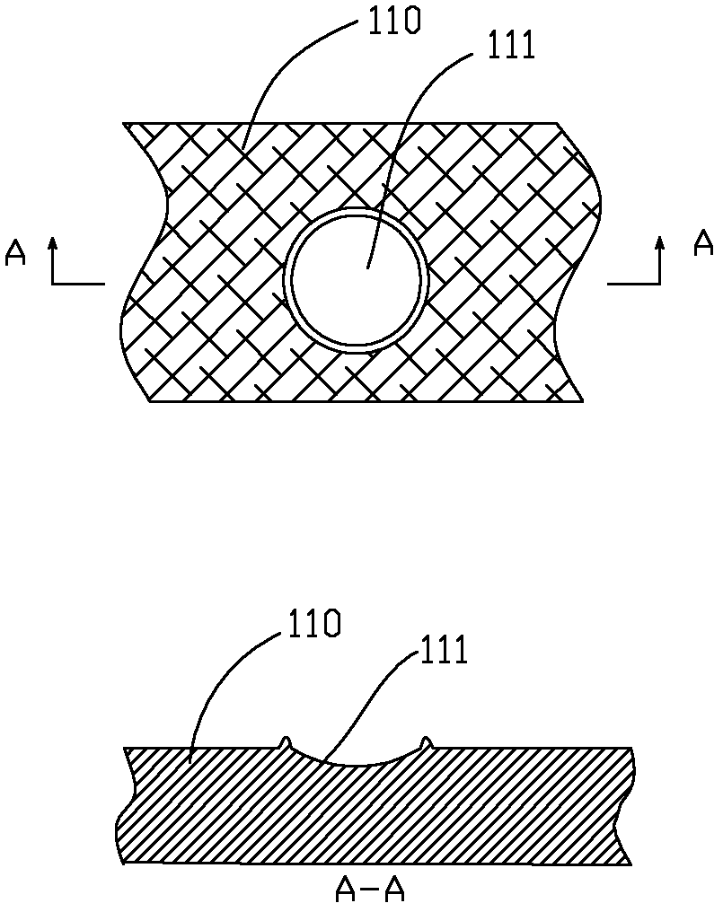
[0032] Step S102, using a laser to print a plurality of first-order dots 211 on the substrate 210, where the laser can be a pulsed laser, and the distribution of the first-order dots 211 on the substrate 210 is designed according to different backlight modules, such as uniform distribution with non-uniform distribution.

[0033] Step S103, using a laser to form a second-order dot 212 in each first-order dot 211, the radius of the second-order dot 212 is smaller than the radius of the first-order dot 211, and the second-order dot 212 is set in the middle of the first-order dot 211. After the first-order dots 211 and second-order dots 212 on the substrate 210 are formed, the mold core is completed. The dots of the mold core inc...

Embodiment 2

[0037] Please refer to Figure 6-8 , the method for forming the light guide plate 320 in this embodiment is similar to that in Embodiment 1, except that a third-order dot is added to the core of this embodiment. In this embodiment, the method for manufacturing a light guide plate includes the following steps:

[0038] Step S201 , providing a substrate 310 .

[0039] Step S202 , using a laser to print a plurality of first-order dots 311 on the substrate 310 .

[0040] Step S203, using a laser to form a second-order dot 312 in each first-order dot 311, the radius of the second-order dot 312 is smaller than the radius of the first-order dot 311, and the second-order dot 312 is set in the middle of the first-order dot 311.

[0041]In step S204 , after forming the first-order dots 311 and the second-order dots 312 inside the first-order dots 311 on the substrate 310 , a third-order dot 313 is formed in the second-order dots 312 by using a laser. The radius of the third-order dot...

Embodiment 3

[0045] Please refer to Figures 9 to 11 , the method of forming the light guide plate 420 in this embodiment is similar to that of Embodiment 1, the difference is that each first-order dot of the mold core in this embodiment is provided with two second-order dots. In this embodiment, the method for manufacturing a light guide plate includes the following steps:

[0046] Step S301 , providing a substrate 410 .

[0047] Step S302 , using a laser to print a plurality of first-order dots 411 on the substrate 410 .


PUM


Abstract

A manufacture method of a light guide plate comprises the following steps of providing a substrate; forming first order dots, wherein the first order dots are formed by utilizing different positions of a laser on the substrate; forming at least one second order dot so as to form a mold insert, wherein the second order dots are formed in the first order dots by utilizing the laser, and the radius of each second order dot is smaller than that of each first order dot; and utilizing the mold insert to form the light guide plate, wherein the power of the laser forming the second order dots is 55%-85% of the power of the laser forming the first order dots. The dots can be manufactured to be two-order or multiple-order dots, depend on a processing power range of the laser, and the range is larger, the more formed dot orders are. The light guide plate manufactured by means of the manufacture method has high outgoing light brightness and good outgoing light uniformity.

Description

【Technical field】 [0001] The invention relates to the field of backlight modules, in particular to a light guide plate applied to a backlight module and a manufacturing method thereof. 【Background technique】 [0002] With the development of science and technology, liquid crystal displays are used more and more widely. People also have higher and higher requirements on the display quality of liquid crystal displays. The display quality of a liquid crystal display has a lot to do with the quality of the surface light source provided by the backlight module. The brightness and uniformity of the surface light source provided by the backlight module are also affected by the light guide plate. In order to improve the brightness and uniformity of light output from the backlight module, dots are generally designed on the light guide plate. The dots on the light guide plate are generally made by printing, laser or injection molding. When using the injection molding method to make...

Claims


Application Information

Patent Timeline
Patent Type & Authority Applications(China)
IPC IPC(8): G02B6/00
Inventor 赵丽红陈俊伟张立典
Owner YANGXIN TECH SUZHOU
Why Eureka
Try Eureka