Multi-view stereoscopic display

A stereoscopic display and multi-view technology, applied in stereoscopic systems, stereophotography, instruments, etc., can solve the problems of high cost and large space

Active Publication Date: 2013-07-17
DELTA ELECTRONICS INC
View PDF2 Cites 11 Cited by
  • Summary
  • Abstract
  • Description
  • Claims
  • Application Information

AI Technical Summary

Problems solved by technology

In order for each projector to project onto the entire screen, a certain projection distance is required. However, when the screen increases, the nu

Method used


Image

  • Multi-view stereoscopic display
  • Multi-view stereoscopic display
  • Multi-view stereoscopic display

Examples


Example Embodiment

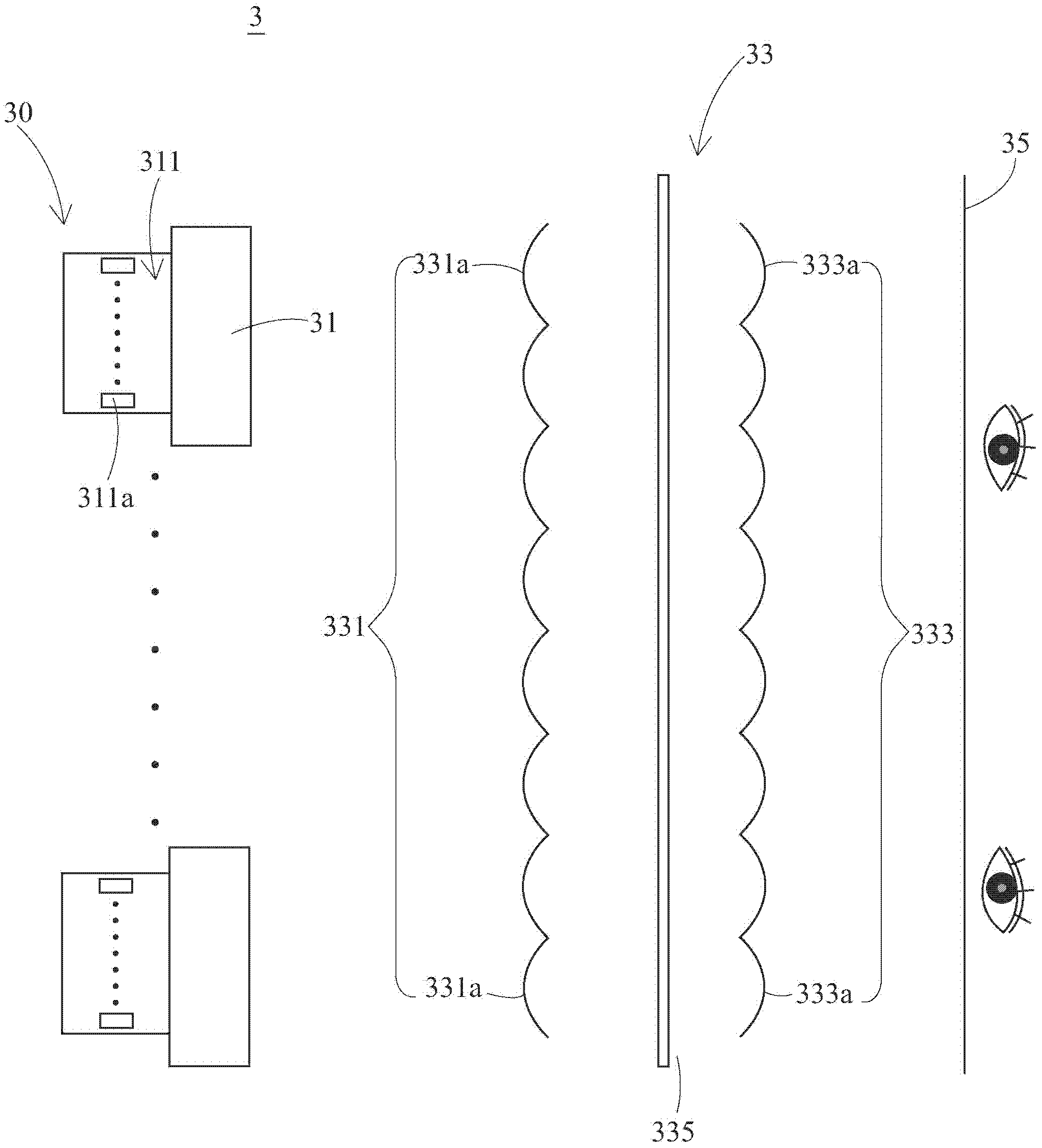
[0050] Such as image 3 Shown is a schematic diagram of the multi-view stereoscopic display 3 of the present invention. As shown in the figure, the present invention mainly includes a projection device array 30 and a pair of lenticular lens array 33. The projection device array 30 includes a plurality of projectors 31, and each projector includes a light source array 311. The light source array is composed of a plurality of light sources 311a. The light generated by the plurality of light sources 311a respectively passes through the plurality of projectors 31 toward a pair of The lenticular lens array 33 is projected, and then the light is projected from the pair of lenticular lens arrays 33 toward a divided viewing area 35; a pair of lenticular lens arrays 33 are arranged between the projection device array 30 and the divided viewing area 35, the purpose of which is to make Each position on the divided viewing area 35 can obtain part of the light projected by each light source...


PUM


Abstract

The invention provides a multi-view stereoscopic display which includes a projection device array and a pair of cylindrical lens arrays, wherein the projection device array comprises a plurality of projectors, each projector comprises a light source array which is composed of a plurality of light sources, light rays generated by the plurality of light sources are projected to a partition visual area respectively through the plurality of projectors, and the pair of cylindrical lens arrays is arranged between the projection device array and the partition visual area, so that every position of the partition visual area can obtain part of the light rays projected by the light sources.

Description

technical field [0001] The present invention relates to a multi-view stereoscopic display, in particular to a multi-view stereoscopic display combined with a time multitasking method and a multi-projector method. Background technique [0002] According to the visual characteristics of human eyes, when both eyes watch the same image at the same time, the images seen by the two eyes will be slightly different because the distance between the two eyes is about 65mm, forming a stereoscopic image. Stereoscopic display technology can be divided into stereoscopic and auto-stereoscopic. The auto-stereoscopic display technology can be further subdivided into spatial multiplex and multiple projectors according to the imaging method. projectors) and time multitasking (time-multiplex). [0003] The existing spatial multi-tasking stereoscopic display technology uses parallax barriers to control the direction of light, and projects images from different angles to different positions in t...

Claims


Application Information

Patent Timeline
IPC IPC(8): G03B35/20G02B27/22H04N13/04
Inventor 黄俊杰
Owner DELTA ELECTRONICS INC
Why Eureka
Try Eureka