Drive circuit, drive method and display device

A technology of drive circuit and gate drive circuit, which is applied in the direction of static indicators, instruments, etc., can solve the problems of low refresh rate and long time of display devices, and achieve the effect of high image display, increased refresh rate, and high refresh rate

Active Publication Date: 2013-07-17
BOE TECH GRP CO LTD +1
View PDF5 Cites 41 Cited by
  • Summary
  • Abstract
  • Description
  • Claims
  • Application Information

AI Technical Summary

Problems solved by technology

Assuming that there are m rows of scanning lines and n rows of data lines, for a large-sized display device, it takes a long time to s

Method used


Image

  • Drive circuit, drive method and display device
  • Drive circuit, drive method and display device
  • Drive circuit, drive method and display device

Examples


no. 1 example

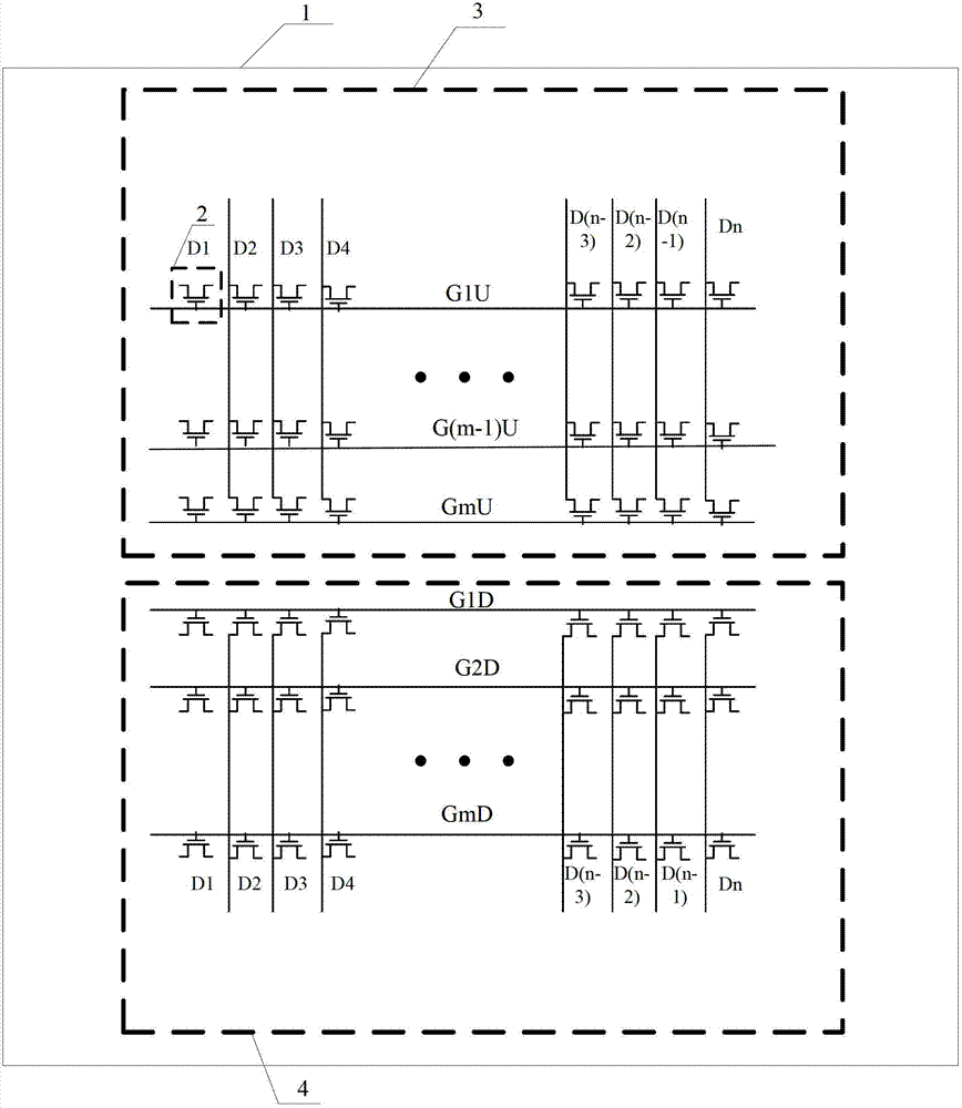
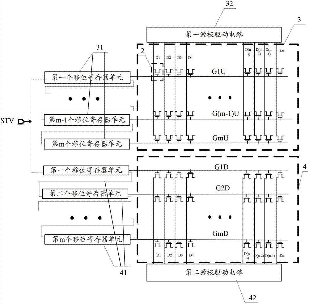
[0065] see image 3 , the driving circuit provided in the first embodiment includes:

[0066] The m gate scanning lines connected to the pixels in the first display area 3 (such as image 3 G1U, G2U, G3U, ... G(m-1) U, Gm U), n data signal lines (such as image 3 D1U, D2U, D3U, D4U, ..., D(n-3)U, D(n-2)U, D(n-1)U, Dn U), and connected to the n data signal lines The first source drive circuit 32;

[0067] The m gate scanning lines connected to the pixels in the second display area 4 (such as image 3 In G1D, G2D, G3D, ... G(m-1) D, Gm D), n data signal lines (such as image 3 D1D, D2D, D3D, D4D, ..., D(n-3)D, D(n-2)D, D(n-1)D, Dn D), and connected to the n data signal lines The second source driver circuit 42.

Embodiment 1

[0068] The gate drive circuit provided by Embodiment 1 is composed of 2m shift register units (Shift Register), and the m shift register units corresponding to the first display area 3 are the first shift register 31; and the second display area 4 The corresponding m shift register units are the second shift register 41;

[0069] The first shift register unit in the first shift register 31 is connected with the first or m shift register unit in the second shift register 41; or the m shift register unit in the first shift register 31 The bit register unit is connected to the first or the m shift register unit in the second shift register 41; the m shift register units in each shift register are cascaded with each other; that is, the first shift register The first shift register unit to the mth shift register unit in 31 are cascaded with each other (connected end to end in sequence); the first shift register unit to the mth shift register unit in the second shift register 41 Th...

Embodiment 2

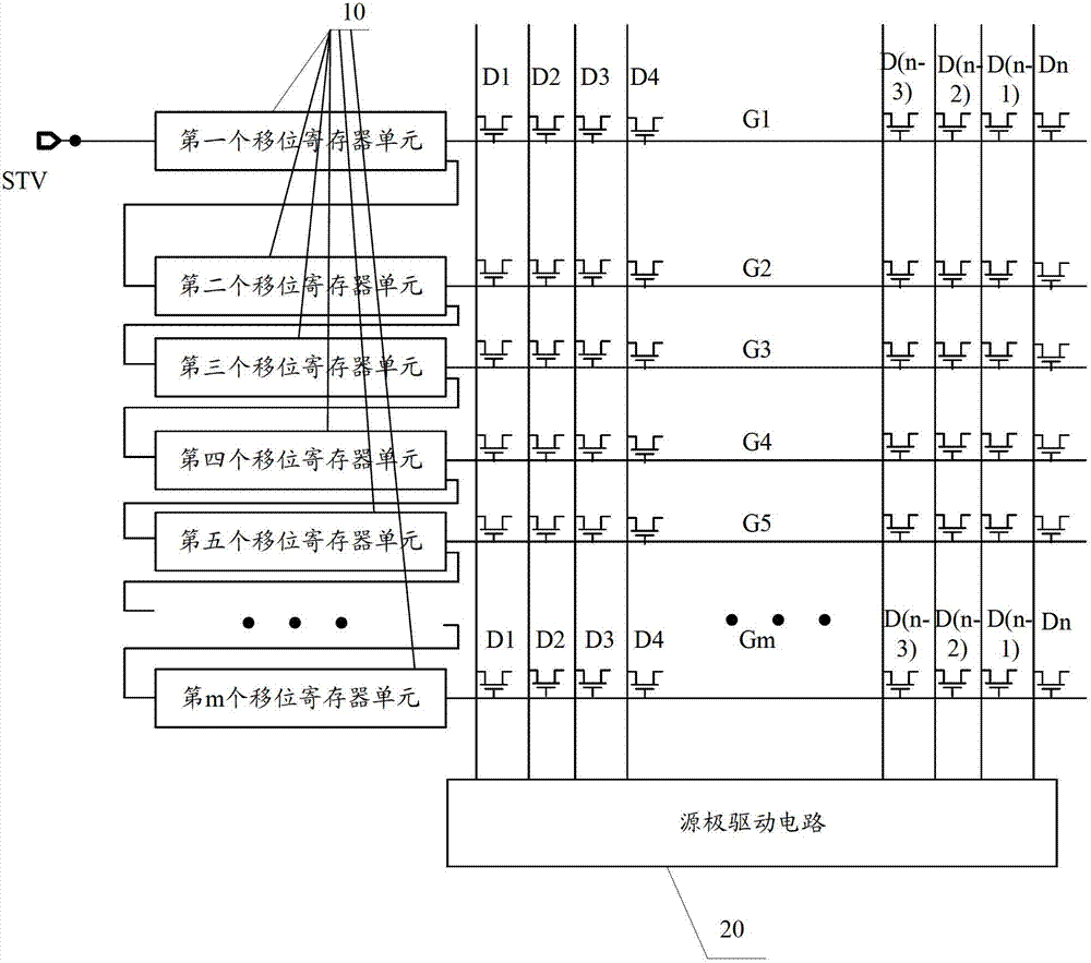
[0081] see Figure 5 , the gate drive circuit is composed of a shift register, the shift register is composed of m mutually cascaded shift register units, and the m shift register units are connected with the m gate scanning in the first display area 3 The lines are connected in one-to-one correspondence, and at the same time are connected in one-to-one correspondence with the m gate scanning lines in the second display region 4 .

[0082] Figure 5 In the driving circuit shown, the first grid scanning line of the first display area is connected to the first grid scanning line of the second display area, and the second grid scanning line of the first display area is connected to the second grid scanning line of the second display area. The second gate scanning line is connected until the mth gate scanning line of the first display area is connected with the mth gate scanning line of the second display area, and the scanning signal is input from the first gate scanning line. ...


PUM


Abstract

The invention discloses a drive circuit, a drive method and a display method. The drive circuit, the drive method and the display method are used for improving refreshing frequency of scanning signals of the drive circuit. The drive circuit is used for driving pixels on an array substrate to display an image; the array substrate comprises a first display region and a second display region; the circuit comprises m lines of grid scanning lines and n lines of data signal lines which are connected with the pixels of the first display region, m lines of grid scanning lines and n lines of data signal lines which are connected with the pixels of the second display region, a grid drive circuit which is connected with all grid scanning lines, and a first source drive circuit and a second source drive circuit which drive the pixels on the array substrate; and the grid drive circuit outputs scanning signals to 2m grid scanning lines line by line simultaneously, and the first source drive circuit and the second source drive circuit output data signals to the data signal lines which are connected with the first source drive circuit and the second source drive circuit respectively, wherein m and n are positive integers.

Description

technical field [0001] The present invention relates to the field of display technology, in particular to a driving circuit, a driving method and a display device. Background technique [0002] In the field of display technology, Thin Film Transistor-Liquid Crystal Display (TFT-LCD) and Organic Light Emitting Display (OLED) are two main flat panel display devices. [0003] As people's demands for large-size and high-resolution display devices continue to increase, large-size display devices are also developing rapidly. Currently, one of the factors restricting large-sized display devices with high performance and high resolution is the refresh rate. The refresh rate is the number of times the screen is refreshed per second. Different sizes of display devices have different refresh rate requirements. For large-sized displays such as 50 inches or more, a higher refresh rate is required to meet better visual requirements. [0004] The refresh rate is related to the structure ...

Claims


Application Information

Patent Timeline
IPC IPC(8): G09G3/20
CPCG09G3/3266G09G2300/0426G09G2310/0205G09G2310/0221G09G2310/0286
Inventor 胡理科祁小敬
Owner BOE TECH GRP CO LTD
Why Eureka
Try Eureka